Model dpc3500, Wiring connections, Communications – Super Systems DPC3500 User Manual
Page 4
Model DPC3500
Continuous Low-Range Dew Point Analyzer
PRODUCT MANUAL
Super Systems, Inc.
DPC 3500
Manual # 4551B
Page 4 of 5
Wiring Connections:
The power and communications wires for the sensor are connected to a plug that
is attached to the head of the sensor. The wires will already be attached to this
plug at SSi, however for reference the wiring for this plug is:
Sensor Plug Terminal #1: Green Wire (to location #1291 on terminal strip)
Sensor Plug Terminal #2: White Wire (to location #1281 on terminal strip)
Sensor Plug Terminal #3: Red Wire (to location #1261 on terminal strip)
Sensor Plug Terminal #4: Black Wire (to location #1271 on terminal strip)
20 feet of sensor wire is included with the unit, however it is capable of operating
over substantially longer distances if required. When attaching the necessary
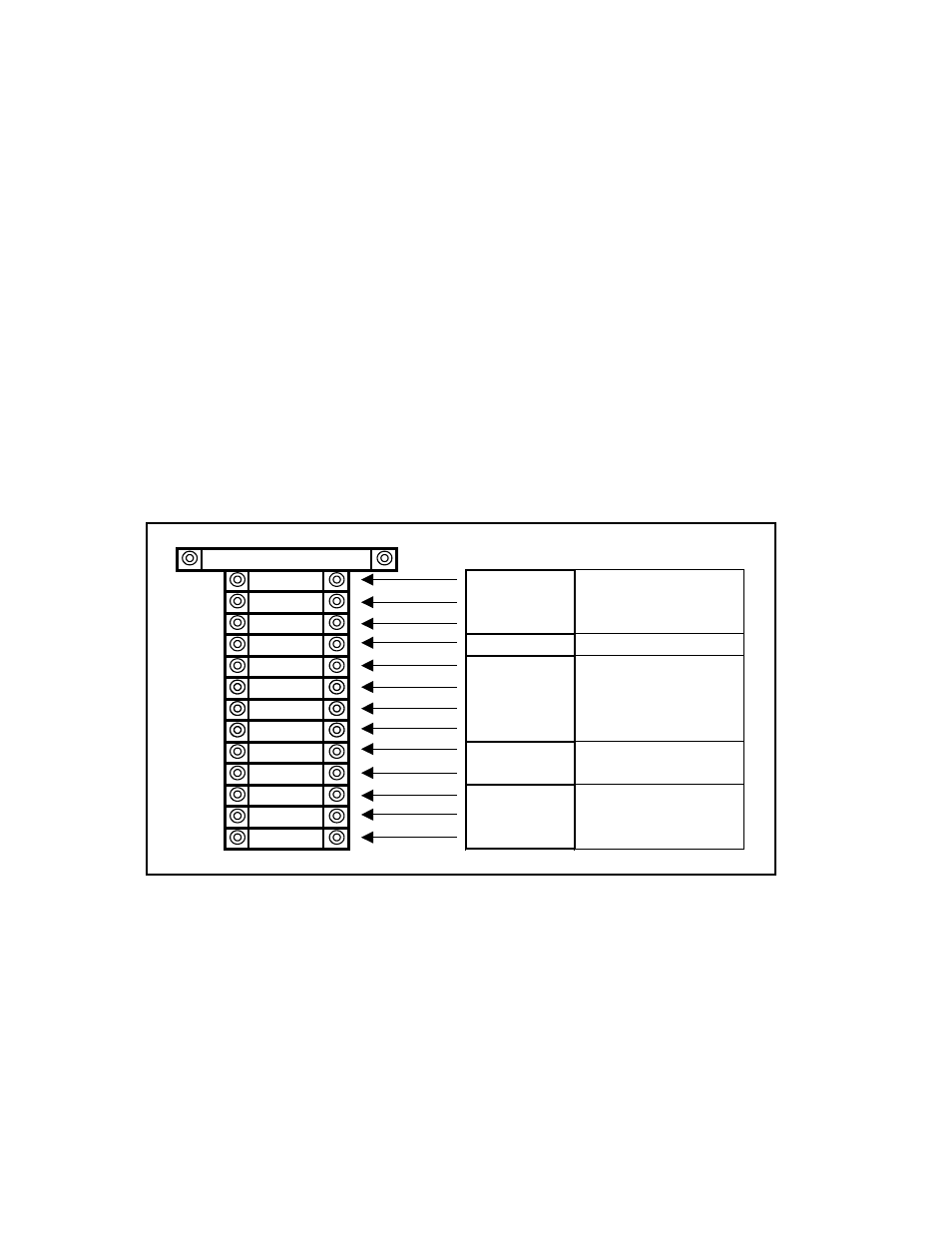
wires to the terminal strip inside the panel, all connections should be made
according to the following diagram:
Communications:
The 4-20 mA output correlates to a dew point range of –148°F to 32°F (–100°C
to 0°C).
1.0 AMP
1000
Line
1002
Neutral
GND
Ground
SPARE
N/A
1261
Red
1271
Black
1281
White
1291
Green
1331
Positive
1341
Negative
1361
Common
1371
Receive Data
1381
Transmit Data
120V
1 PHASE
60 HZ
FROM SENSOR
CONNECTOR
4-20 mA
OUTPUT
RS 232
COMMUNICATIONS
UNUSED