Tecfluid LT Series User Manual
Page 2
OPERATION
The variations of level are followed by the internal float that, by means of a magnetic field, acts on
the indicator.
2
RECEPTION
The LT/LTL series are supplied suitably packed for transport. They are supplied with the float
blocked in its bottom position by means of a stop introduced into the lower side coupling.
BEFORE MOUNTING ON THE TANK, THIS STOP MUST BE REMOVED.
INSTALLATION
Important: Check that the maximum working pressure is below the limit shown on the
identification label of the equipment. Check that the maximum working temperature of the
liquid is within the limits given in the following table.
The working temperatures are given for an ambient temperature of 20ºC.
The fittings to the tank must be ALIGNED and PERPENDICULAR.
Flange bolts should be tightened progressively in a criss-cross manner to avoid creating tensions.
With threaded connections, they should be tightened progressively and together.
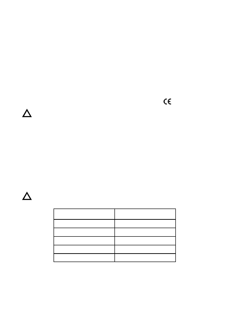
MATERIALS
LIQUID TEMPERATURE
RANGE
EN 1.4404 (AISI-316L)
-20 ºC…...150 ºC
PVC
0 ºC…...45 ºC
PP
-10 ºC…...90 ºC
PVDF
-20 ºC…...135 ºC
PTFE
-60 ºC…...150 ºC
TECHNICAL DATA
• Mounting: Vertical, on the side of the tank.
• Fittings: EN 1092-1 DN-25 Flanges
1” BSP/NPT Threads
Others on demand:
• Liquid Density: 0.45 a 3 kg/l
• Liquid viscosity: maximum 1500 mPa.s
• Precision: ±3 mm
• Materials: EN 1.4404 (AISI-316L). On demand: PTFE, PVC, PP, PVDF
• Pressure: PN-16 (in EN 1.4404)
PN-10 (in PVC y PP)
On demand: PN-400
• Length: Maximum 6000 mm. On demand up to 15000 mm in EN1.4404
•
Conforms with the Pressure Equipment Directive 97/23/EC.
This equipment is considered as being a pressure accessory and NOT a safety accessory
as defined in the 97/23/EC directive, Article 1, paragraph 2.1
.3.
!
!
0830