Tecfluid DFD-2 User Manual
Page 5
5
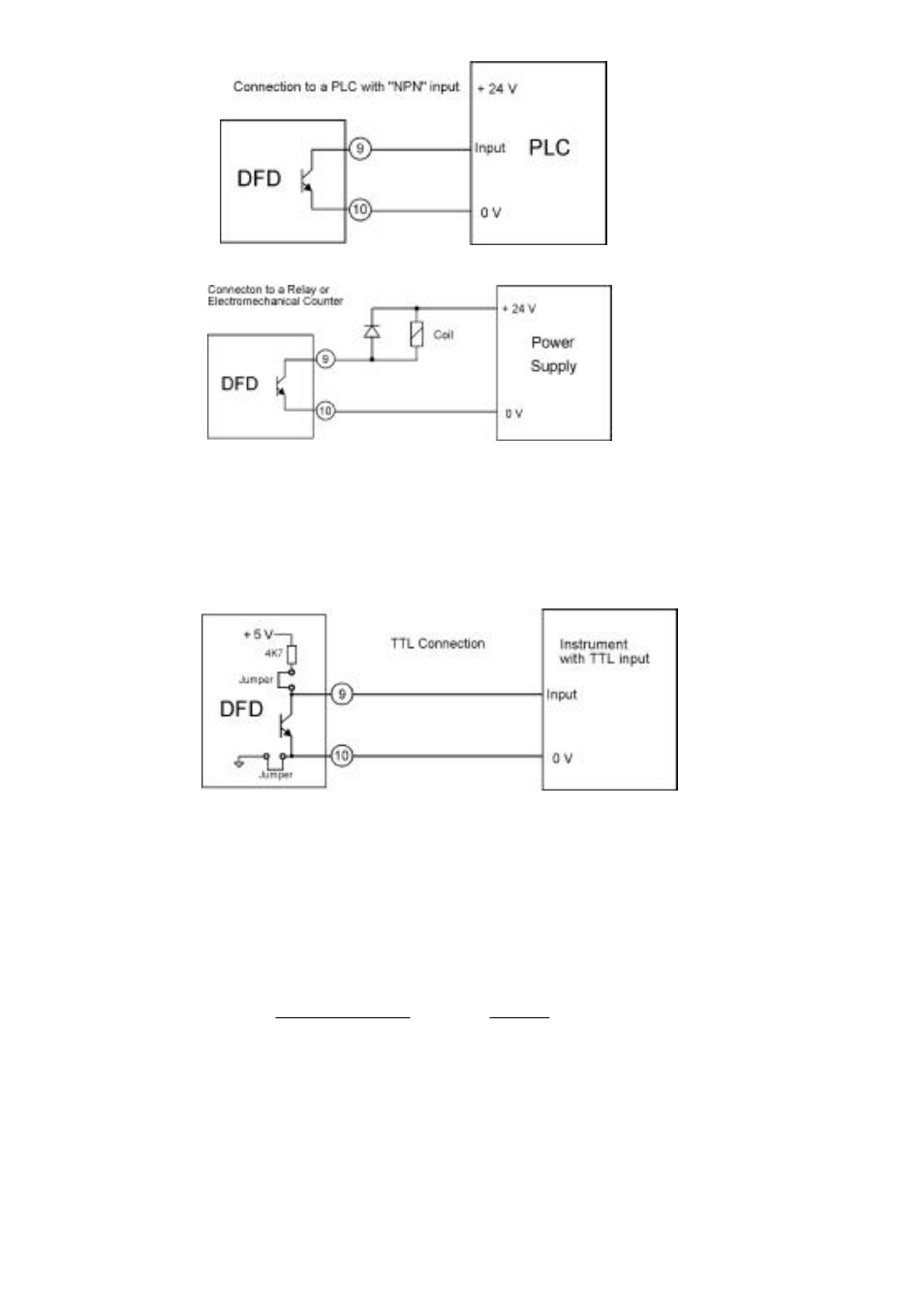
2.3.2 TTL output
For the TTL (0 to 5 volts) output, terminal 10 is the common and terminal 9 is the live output.
For this mode of output the jumpers JP3 and JP4 must be placed across the pins.
3. SETTING UP
Once the instrument is installed the only thing that has to be done is setting the multiplication factor
which must be applied to the input frequency to obtain the output frequency. For example, if we have
a turbine flowmeter which gives 752.22 pulses per litre and we want to totalize litres with a counter
the relationship between the output and input frequencies will be 1/752.22; thus the factor (K) to be
introduced will be 0,001329398. Given that we only have four significant digits this factor will be
rounded off to 0,001329.
0.001329
=
752.22
1
=
pulses
input
pulses
output
=
K
To introduce this conversion factor we have four BCD coded switches and a jumper with four
positions. With the four BCD coded switches we select the four significant digits and with the jumper
we select the number of zeros between the decimal point and the first significant digit. To get to the
switches, a screwdriver can be used to lever out the top cover, which is just clipped in its place.