Tt2400xquickguide.pdf, Connector assembly, Waterproof rj-45 – Teletronics TT 2400X Quick Start User Manual
Page 2: Hardware installation, Web control interface, Quick installation, Assembly instruction
Re-using items (1) and (2) from the safety cap, assemble the waterproof RJ-45
connector as shown below:
NEMA 4 Enclosure
Safety Cap
2
1
2
3
1
4
5
6
Waterproof RJ-45
Connector Assembly
Follow the procedure below to install your TT™2400X device:
Note: The TT™2400X now supports MDI/MDI-X and no longer require the use
of cross over cable to connect directly with a computer.
1. Select a suitable place on the network to install the TT™2400X. For best wireless reception
and performance the external antenna should be positioned within Line of Sight from the
AP with proper alignment.
2. Connect the TT™2400X to the ODU side of the PoE Injector via a straight Ethernet cable
(Cat-5), then connect the NET side of the PoE Injector to either a computer or an Ethernet Switch.
Check the LEDs on the TT™2400X to confirm if the status is okay. At this point the PWR and LAN LEDs
should be on green. The WLAN light should light up once the unit is associated wirelessly with another
wireless device. However at this point the unit is still in factory default setting so do not the alarmed
that the WLAN light doesn’t light up.
3. Connect the 48VDC power adapter to the power jack on the PoE injector to power on the TT2400X.
For detailed instructions on how to configure the TT™2400X, please refer
to www.teletronics.com/Support.html
Hardware Installation
Default IP Address in Client Bridge Mode (SU): 192.168.3.1
Web Control Interface
Always double check for any missing parts before deployment. Next step is to set up the
computer Ethernet interface for configuring the TT™2400X.
Quick Installation
Default IP Address in Access Point Mode (AP): 192.168.1.1
Default Login/Password: Nothing needs to be typed in for login and password authentication.
http://192.168.3.1
http://192.168.1.1
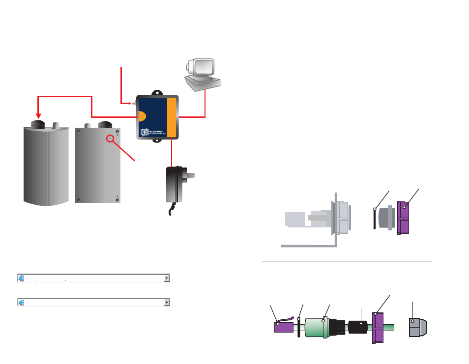
Assembly Instruction
I. Assembly Diagram
*Actual parts may vary, please use
this diagram for general guidance.
PC
EXTERNAL ANTENNA
CONNECTOR
POWER OVER ETHERNET
CONNECTION
DC POWER
CONNECTION
TO NETWORK
GROUND
CONNECT TO
GROUND
TOP VIEW
BOTTOM VIEW
PWR
NET
ODU
WITH SURGE
PROTECTION
PoE