Teo PS-50 ISDN User Manual
Page 3
13-280105 Rev. A
Page 3
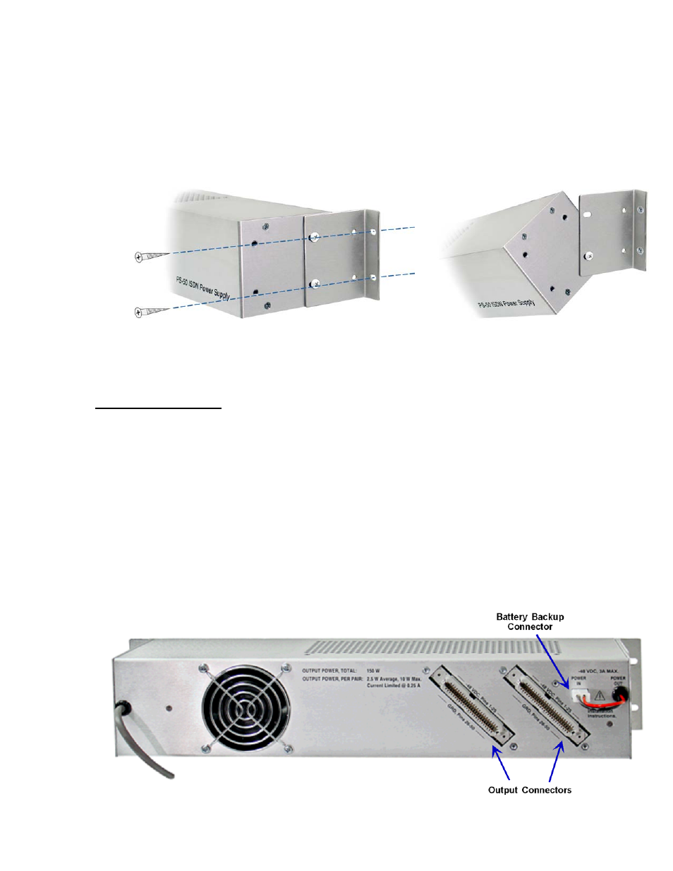
Wall Mounting
1. Attach the long side of the mounting brackets to the rear mounting holes on the PS-50 as shown in
Figure 3, using the supplied mounting bracket screws.
2. Mount the PS-50 to the wall using suitable fasteners. Do not obstruct the fan on the rear panel of
the unit.
3. To attach cables, remove the top mounting bracket screw from each side as shown, then tilt the PS-50
forward.
Figure 3 – Wall Mounting
Output Connections
Output connections are supplied on two 50-pin ribbon connectors.
1. Fill out the Number of Units column in Table 2 (on the back page) with the number of telephones, add-
on devices, NT1s, and/or Battery Backup units that will be powered from the PS-50. Multiply the
number of units by the wattage shown for each device, and enter the result in the Total Power column.
Add all of the entries in the Total Power column to determine the output power required form the PS-
50.
Total power for all devices must not exceed 150 watts.
2. Connect a male-ended ribbon cable from each 50-pin connector on the rear panel to a 50-pin
punchdown block. See Table 1 for connector pinout.
3. Cross-connect power pairs from the power punchdown block to the blocks for the devices to be
powered.
Observe correct polarity.
Figure 4 – PS-50 Rear Panel