Ht heating module, Installation procedures – Thermon HT Heating Module User Manual
Page 3
3
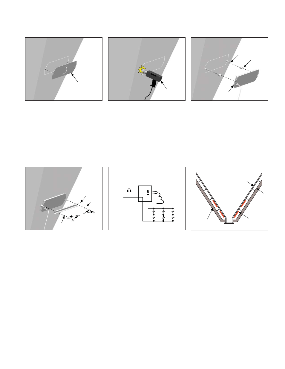
1.
Have template and heating system layout
drawing available. Select the correct sized
template. Position installation template on
hopper wall per layout drawing and mark stud
locations. If two or more modules are to be
placed in one area, care should be taken to
insure proper fi t of all modules. By marking the
outline of each template with chalk or crayon
on the hopper wall, clearances can be verifi ed
prior to welding of studs.
2.
Weld studs in place per the manufacturer's
recommendations.
Notes:
•
Sandblasting of hopper surface or grinding
of welding beads or weld splatter is NOT
required for proper installation of the
HT Heating Modules. However, to provide
maximum heat transfer effi ciency, it is
recommended to install the HT Heating
Module on a fairly clean, smooth surface.
3.
Place spacer on each stud and then place HT
Heating Module over studs.
4.
Assemble mounting components (supplied
with each module) in the following order:
•
Place reinforcing channel over module and
studs.
•
Place washer on each stud.
•
Secure with one nut per stud and torque
down with 20-30 foot pounds.
•
Add second nut to each stud and tighten.
Carefully route lead wires to junction box and
connect to the terminal strip according to the
layout drawing. See typical wiring schematic.
Spacer
Stud
HT Heating Module
Stud Welder
(By Others)
Installation Template
Reinforcing Channel
Washer
Nuts
Washer
HT Heating Module
INSTALLATION PROCEDURES
Typical Wiring Schematic for Heating Modules
L1
L2/N
IMPORTANT:
See Thermon project specifi c heater layout
and wiring drawings for actual heater wiring.
Notes:
1. Route lead wires to junction box(es) according to project specifi c heater layout drawing. CAUTION: Do not rotate the feed through
fi tting which supports the heater wiring.
2. During heater installation, heaters should not be left exposed to rain, snow, moisture, etc..
3. Electrical insulation resistance test (megger) and resistance (Ohms) should be done on each heater per project installation manual.
Hopper Insulation Design
Heating Module
Heating Insulation
IMPORTANT:
The design of the hopper heating
system is based on the transfer of heat into the
hoppers via convection and conduction in the
air spaces between each stiffener to provide an
“oven” effect to ensure even distribution of heat.
It is important that the insulation be properly
sealed at each stiffener level to prevent drafts
or chimney effects. Allow 2 inch minimum
air space for heaters. (See project installation
manual for additional details).
2" Minimum Air Space