Terminator, Zt-mi-wp, Installation procedures – Thermon ZT-MI-WP Terminator User Manual
Page 4
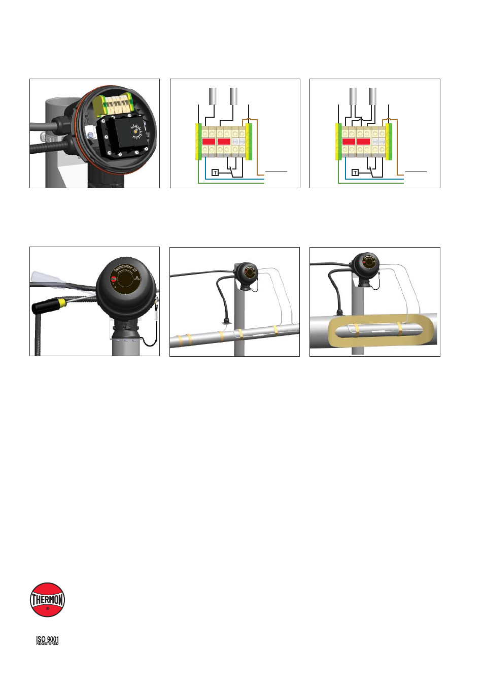
10.
Install junction box lid and twist hand tight.
Insert screwdriver into ratchet slots located
on side of junction box base. Use screwdriver
to ratchet on junction box lid. Lid will rotate
30 degrees. To remove lid, repeat steps in the
opposite direction.
9.
Install thermostat and complete system wiring.
Terminal set screws shall be tightened to a
torque value of 1.4 Nm (12.4 lb-in). See wiring
diagrams for details. Set thermostat at desired
setpoint.
Terminator
TM
ZT-MI-WP
INSTALLATION PROCEDURES
11.
Fix thermostat bulb and capillary tube to pipe.
Specifi cations and information are subject to change without notice. Form PN50855U-0113
THERMON . . . The Heat Tracing Specialists
®
www.thermon.com
Corporate Headquarters
100 Thermon Dr.
•
PO Box 609
San Marcos, TX 78667-0609
•
USA
Phone: +1 512-396-5801
European Headquarters
Boezemweg 25
•
PO Box 205
2640 AE Pijnacker
•
The Netherlands
Phone: +31 (0) 15-36 15 370
For the Thermon offi ce nearest you
visit us at . . .
www.thermon.com
Wiring Details: Single Core
17
25
I
I 2
GD
Ex d
b eb IIC
T5-T6, Ex tb IIIC
T10
0°C
-T8
5°
C,
F
M
1
0A
TE
X0
0
5
8
X
IEC
Ex F
MG 1
0.0022X
Ex db
eb I
IC T
5-T
6,
Ex
tb
II
IC
T
10
0°
C
-T
8
5
°C
PN 27656
Te
rm
inator Z
T
Fo
r u
se
as
an
adj
ustable
control/lim
iter th
erm
ost
at
IP
6
6 -
60
°C
≤
Ta ≤
+50
°C T5, 100°C; -60°C ≤
Ta
≤
+4
0°
C
T6
, 8
5°
C
1
7
2
5
II 2
G
D E
x db
eb IIC
T5-T6, Ex tb IIIC T100
°C-T
85
°C
, F
M
1
0A
TE
X0
0
5
8
X
IE
CE
x F
MG
10.0
022X
Ex db eb I
IC T
5-T
6,
Ex
tb
II
IC
T
10
0°
C
-T
8
5
°C
PN 27656
Te
rminator Z
T
Fo
r u
se
as
an
adjust
able control/li
mite
r th
erm
os
ta
t
IP
6
6
-6
0
°C
≤
Ta
≤ +
50°C
T5, 100°C; -60°C ≤ Ta
≤
+4
0°
C
T6
, 8
5°
C
12.
Seal penetration through insulation cladding.
Power Supply
L1
N
PE
Heat Trace #1 Heat Trace #2
2
2
4 L1
N
N
PE
PE
Power Supply
L1
N
PE
Heat Trace #1 Heat Trace #2
2
2
4 L1
N
N
PE
PE
Wiring Details: Dual Core
17
25
I
I 2
GD
Ex d
b eb IIC T
5-T6, Ex tb III
C T1
00°
C-T
85
°C
, F
M
1
0A
TE
X0
0
5
8
X
IEC
Ex F
MG 1
0.0022X
Ex db
eb
IIC
T5
-T6
, E
x t
b
III
C
T1
00
°C
-T
8
5
°C
PN 27656
Te
rm
inator Z
T
Fo
r u
se
as
an
adj
ustabl
e control/lim
iter th
erm
ost
at
IP
6
6 -
60
°C
≤
Ta ≤
+50
°C T5, 100°C; -60°C ≤
Ta
≤
+4
0°
C
T6
, 8
5°
C
Earth Tag
Earth Tag
Earth Tag
Earth Tag