Terminator, Ecm-p-wp, Installation procedures – Thermon ECM-P-WP User Manual
Page 3
3
Terminator
TM
ECM-P-WP
INSTALLATION PROCEDURES
The Heat Tracing Specialists
®
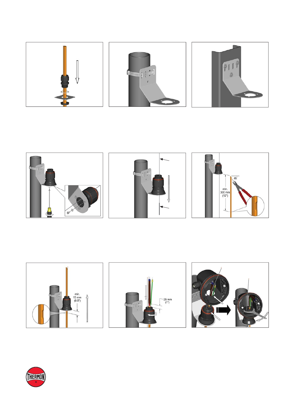
8.
Mount junction box base on expediter.
Make sure to align slots to properly
orient junction box base. Tighten nut
with Terminator-LN-Tool. If mounting
horizontally, threaded gland holes must
face downward.
7.
Terminate cable with appropriate PETK
termination kit. Refer to PETK installation
instructions. Push excess cable back
through expediter. Tighten cap securely.
Tape cable expansion loop to pipe.
4.
Position RTD Sensor(s) in grommet. Do
not pull from the sensor end when routing
through the expediter assembly. Pull
sensor from the lead wire portion.
6.
Insert cable into expeditor. Make
sure bus connection (HPT and FP
only) remains outside of expediter.
Note:
For HPT and FP cable, exchange
grommet in Terminator with grommet
provided in PETK-3-ECM.
5.
Locate bus connection (HPT and FP only)
as shown. Cut end of cable at angle to
aid in piercing grommet. Leave additional
cable for expansion as needed.
3.
Mount expediter to bracket using
M5 x 8mm screws and M5 lock washers.
2b.
Mounting Method 2: Secure wall mount
bracket to mounting surface using
customer supplied screws, fl at washers,
and nuts.
2a.
Mounting Method 1: Secure wall mount
bracket to mounting surface using pipe
band provided with kits.
1.
Slide appropriate IEK insulation entry
kit components onto cable.
RTD
Lead Wire
RTD
Sensor