Installation procedures, Typical heat tracing installation, Receiving, storing, handling – Thermon HSX User Manual
Page 3
3
INSTALLATION PROCEDURES
Cable Type (Catalog No.)
Outer Jacket Color
Voltage (Vac)
HSX 2105-2
Blue
208
HSX 2120-2
Green
208
HSX 2140-2
Red
208
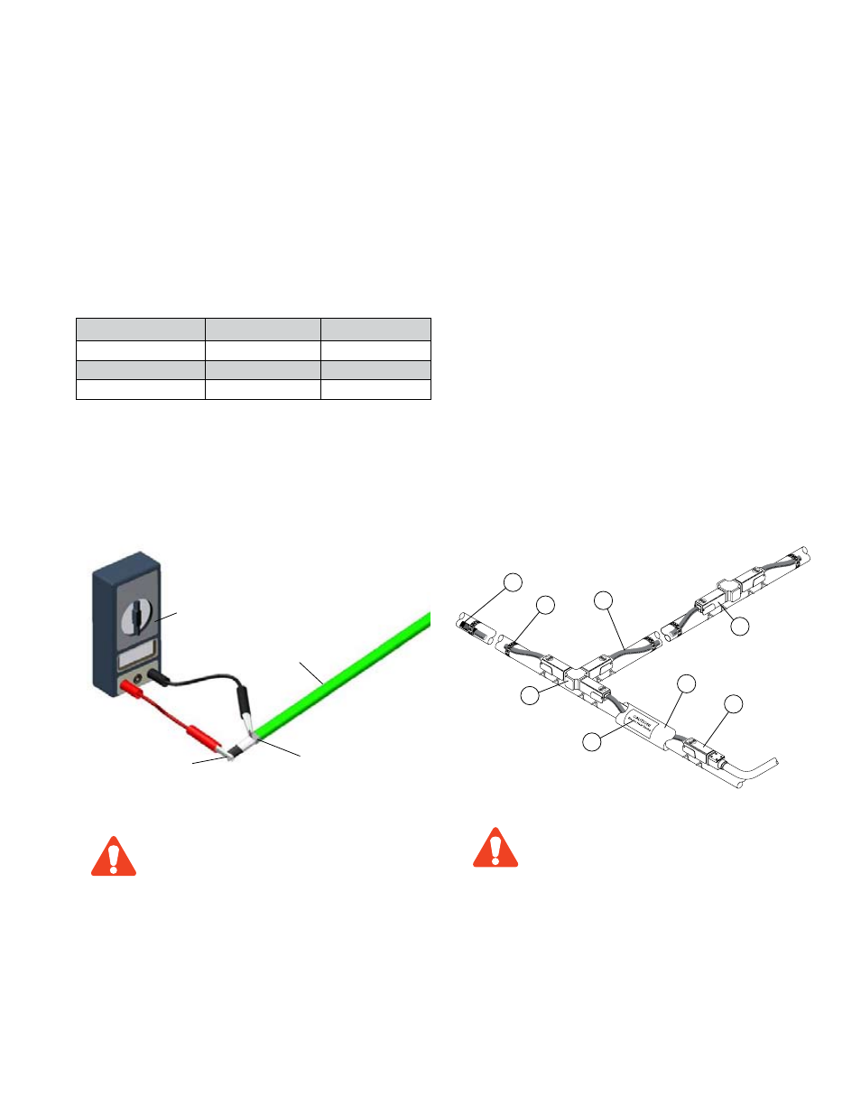
Typical Heat Tracing Installation. . .
A complete electric heat tracing system will typically include
the following components:
1. HSX self-regulating heating cable.
2. PowerSnap1 or PCA-COM power connection kit to
terminate heating cable.
3. TeeSnap or PCS-COM allows three heating cables to be
spliced together.
4. SpliceSnap or PCS-COM allows two heating cables to be
spliced together.
5. ET-6 cable end termination. Each PowerSnap1 and TeeSnap
includes two ET-6 terminations.
6. FT-1 Attachment tape secures cable to pipe; use on
300 mm (12") intervals.
7. CL "Electric Heat Tracing" label peel and stick to insulation
vapor barrier on a 3m (10') interval or as require by code or
specification.
8. Fiberglass thermal insulation and vapor barrier.
The National Electric Code and Canadian
Electrical Code require ground fault protection
be provided for all electric heat tracing.
CAUTION
1
2
8
7
3
6
5
4
Refer to the “HSX Cable Testing Report” for required recording
of test data and circuit information.
Receiving, Storing, Handling . . .
1. Upon receiving heating cable, check to make sure the
proper type and output have been received. All cables are
printed on the outer jacket with part number, voltage rating
and watt output.
DO NOT connect power to heating cable while
it is on reel or in shipping carton.
Bus Wire
Ground Braid
Heater Cable
Megger
2. Visually inspect cable for any damage incurred during ship-
ment. The heating cable should be tested to ensure electri-
cal integrity with at least a 500 Vdc megohmmeter (megger)
between the heating cable bus wires and the heating cable
metallic braid. IEEE 515.1 recommends that the test volt-
age for polymer insulated heating cables be 2500 Vdc.
Minimum resistance should be 20 megohms. (Record 1 on
Cable Testing Report.)
Connect the positive lead of the megger to the cable bus wires
and the negative lead to the metallic braid.
3. Store cable and accessories in a clean dry place where
temperatures will be between -40°C and 60°C (-40°F and
140°F).
CAUTION