Power connection and end termination kit – Thermon RGS-SFK User Manual
Page 2
RGS
TM
-SFK
Power Connection and End Termination Kit
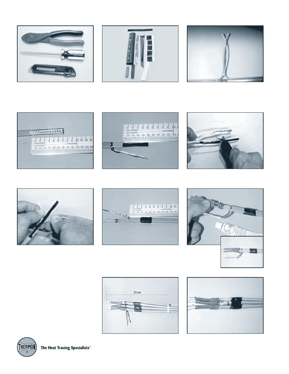
Tools Required for Installation
Crimper/cutter, flat-blade screwdriver,
and utility knife
Kit Contents
(1) Splice/Tee, (1) End Termination
Splice and Tee Connection
Step 1:
Allow 12" (30 cm) of extra length
for each heating cable at the connection
point.
Step 2:
Cut overjackets back a distance
of 3" (70 mm).
Step 3:
Separate braids and twist into pig-
tails. Carefully cut primary jackets back
2" (50 mm).
Step 4:
Skive outer matrix material from
conductors with utility knife.
Step 5:
Peel exposed wires back from
center matrix and cut center matrix away,
leaving bare conductors.
Step 6:
wrap black mastic around each
cable beginning at a distance fo 1"
(25 mm) back from the pigtail (overjacket).
Step 7:
Squeeze
RTV into the
silicone rubber
boots and slide
over cable ends.
Step 8:
Stack the two (or three cables in
the case of a tee) together and tighten
down with two standard tie wraps at
8" (20 cm) and 10" (28 cm) respectively
from the exposed bus wire end.
Step 9:
Twist all the pigtails together. Slide
the large un-insulated lug over the braid
ends in close proximity to the cables and
then crimp. Trim off any extra braid. Bend
pigtail back so that the crimp lug lies down.