Thinklogical Velocitydvi System-3 A/N+ Quick Start Guide User Manual
Velocity dvi-3, Quick start guide, Dvi-d connector 1 dvi-d connector 2
Copyright © 2010. All rights reserved. Printed in the U.S.A. All trademarks and service marks are the property of their respective owners.
QUICK START GUIDE
4
Visit us online at
www.thinklogical.com
for more product information, current updates
and the complete line of Thinklogical™ products.
Receiver
CPU
Power Supply
Digital Video, Audio and Network Extension System
The
Velocity
dvi
Digital Video/Audio/Network Extension System-3 A/N+ from Thinklogical™ permits the placement of a digital monitor or projector, audio devices and 10/100 ethernet up to 1000
meters (3280 feet) away from a controlling computer without loss of resolution. Each system consists of a transmitter and a receiver connected by multi-mode fiber optic cable(s). Dual fiber is used for
some DDC modes to provide communications to and from the transmitter and is required for network connectivity. The receiver unit provides an interface to the display, audio devices and network.
Installation is plug-and-play and no adjustments are necessary.
Each of the Thinklogical™
DVI A/N+ Extension Systems is designed for high resolution video, audio and network extension applications such as remote projection centers, theaters and assembly
halls, and for secure computer installations. It is now possible to position the monitor or projector in any setting from office to lecture hall to boardroom while keeping the computer secure in a
remote, controlled location. All physical connections to the product use industry-standard connectors.
The
Status LEDs on the Tx and Rx units are used to indicate the status of
connections to the extender.
Tx Status LED
·
Green
= Fiber L2 is connected and a good link is established.
·
Orange
= Local Static Mode selected and no fiber link from Rx to Tx (L2 is not
connected) or both DDC mode buttons are held down and the unit is waiting
to reload the default DDC table.
·
Red Flashing
= No Fiber Link from Rx to Tx (Not available in Local Static
mode.)
Rx Status LED
·
Green
= Good Link and DVI device connected to primary port (port on left in
the diagram below).
·
Orange
= No DVI device connected to primary port.
·
Red Flashing
= No Fiber Link from Tx to Rx (L1 is not connected).
Contents
Upon receiving your Thinklogical™
Velocity
dvi
-3 A/N+
Extender System, you
should find the following items:
·
DVI Extender Transmitter
·
DVI Extender Receiver
·
DVI-D Male to DVI-D Male Cable,
2 Meter (CBL00009-002MR)
·
Two CAT5 Cables, 2M (CBL000001-002M)
·
Two 3.5mm Audio Cables
(CBL000016-006FR)
·
Two Universal AC Power Adapters
(PWR-000022-R)
·
DVI Extender Product Manual
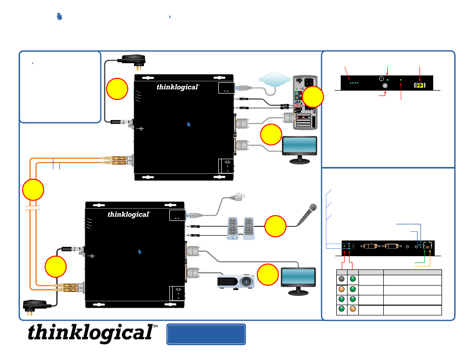
STEP 4:
Connect your
fiber optic cable, up to 1000 meters (available through
Thinklogical™) between the Transmitter and Receiver Units. Do not kink or pinch
the cable and be sure to keep all bend radii to no less than 3 inches.
3
STEP 3:
Connect the supplied
AC
Power Adapter (PWR-
000022-R) to the Receiver
and plug it in to a standard
AC source.
6
5
STEP 1:
Connect one end of a
DVI-D Male to Male Cable to the primary viewing device.
Connect the other end of the cable to the
Primary (left) Receiver DVI-D
connector. A second device can also be installed to the right- side, secondary
port using a similar DVI-D Male to Male cable. If using only one device, it must be
connected to the Primary Port. Turn ON the DVI video device(s).
STEP 5:
Connect the supplied
AC
Power Adapter (PWR-000022-R) to
the Transmitter unit and plug it in to
a standard AC source.
Projector
Acquire Button
·
Used to initiate DDC collection. Works with all modes except Pass-Thru.
Must be pressed after switching between DDC modes.
Select Button
·
Used to select the DDC mode. The modes will cycle through Remote
Dynamic, Remote Static, Pass-Thru and Local Static.
Both Buttons held 5 seconds
·
Holding both buttons for 5 seconds will reload the default DDC table into
the Tx and switch to Remote Static mode.
Fiber-optic
cable ports.
GND
The Primary Port on the Rx is used for DDC. The Secondary Port
carries video data only.
Primary DVI Port DDC
Optional Secondary DVI Port
1
Power Supply
When lit, the solid
green LED indicates
that power is applied.
Transmitter
◄ Line IN
Mic OUT ►
◄ Mic IN
Line OUT ►
2
STEP 2:
Connect your
Mic IN, Line OUT and CAT5 Cable
to the appropriate Receiver ports. Turn the devices ON.
Network
DVI-D Connector 1
DVI-D Connector 2
STEP 6:
Connect one end of a
DVI-D Male to Male
Cable to the Video Source (DVI-D video card).
Connect the other end to the Transmitter’s
DVI
from CPU connector. A local display may also
be connected using the supplied 2 meter DVI-D
Male to Male Cable (CBL-000009-002MR).
VELOCITY-3AN+_Quick_Start_Rev_A
PHONE: 1-800-291-3211
WEBSITE: www.thinklogical.com
EMAIL: [email protected]
RJ45 Network Device*
Network
FOL, TX, RX and LNK/ACT
indicator LEDs
Velocity
MRTS
Technology
Transmitter
DVI from CPU
DVI to Local Display
dvi
Powered by
The Future of Access and Control
Digital Video Extension System – 3A/N+
Mic Out
Line In
100 10
FD COL
Network
DDC Mode
Acquire
Select
REM
LCL
L2 ► Data
L1 ◄ Video/Data
Status
+
5VDC
Power
FOL
TX
RX
LNK/ACT
Velocity
MRTS
Technology
Receiver
DVI to Display
DVI to Display DDC
dvi
Powered by
The Future of Access and Control
Digital Video Extension System – 3A/N+
Line Out
Mic In
100 10
FD COL
Network
DDC Mode
Acquire
Select
REM
LCL
L2 ◄ Data
L1 ► Video/Data
Status
+
5VDC
Power
FOL
TX
RX
LNK/ACT
Secondary
DVI Port
Local Monitor
7
100/10: When lit, speed of link is 100 Mb.
When off, speed of link is 10 Mb.
FD/COL: When lit, indicates operation in Full Duplex.
When off, indicates operation in Half Duplex.
When blinking, indicates Collision.
On the RJ45 connector:
Green LED = Link
Yellow LED (blinking) = Activity
Velocity
dvi-3
A/N+
Connect
L1 to L1
and
L2 to L2
: Optical Fibers available
with ST-, SC- or LC-type connectors.
L1
L2
L1: Data Tx to Rx and Video
L2: Data Rx to Tx
*The Transmitter and Receiver Network Ports can be
used interchangeably as an input or an output.
STEP 7:
Connect the
Line IN and Mic OUT audio cables from
the CPU to the appropriate Transmitter ports. Connect the
Network Cable to an active Network. Ensure that all the devices
are turned on and all system functions are operating properly.
GREEN
GREEN
ORANGE
LCL REM DDC MODE
DESCRIPTION
REMOTE
DYNAMIC
REMOTE
STATIC
PASS-
THRU
LOCAL
STATIC
EDID READ FROM REMOTE DISPLAY
AND UPDATED EACH TIME REMOTE
DISPLAY CHANGES.
EDID READ FROM REMOTE DISPLAY
WHEN ACQUIRE BUTTON IS PRESSED.
ACTS AS A DIRECT CONNECTION
BETWEEN CPU AND DISPLAY. NO
EMULATION IS PERFORMED.
EDID READ FROM LOCAL DISPLAY
WHEN ACQUIRE BUTTON IS PRESSED.
OFF
GREEN
GREEN
GREEN
ORANGE
Active
Network