Thinklogical Velocitydvi System-3 A/V+ Quick Start Guide User Manual
Velocity dvi, Quick start guide, Velocity
Copyright © 2009. All rights reserved. Printed in the U.S.A. All trademarks and service marks are the property of their respective owners.
PHONE:
(800) 291-3211
WEBSITE:
www.thinklogical.com
EMAIL:
QUICK START GUIDE
All physical connections to the product use industry-standard connectors.
4
Visit us online at
www.thinklogical.com
for more product information, current updates
and the complete line of Thinklogical products.
TM
Receiver
CPU
Power Supply
Digital Video Extension System -
Each of the Thinklogical™ DVI A/V+ Extender systems is designed for high resolution video and audio extension applications such as remote projection centers, theaters and assembly halls, and
for secure computer installations. It is now possible to position the monitor or projector in any setting from office to lecture hall to boardroom while keeping the computer secure in a remote,
controlled location.
The status LEDs near the USB port on the Tx and Rx units are
used to indicate the status of connections to the extender.
Tx Status LED
Green
= Fiber L2 is connected and a good link is established.
Orange
= Local Static Mode selected and no fiber link from Rx
to Tx (L2 is not connected) or both DDC mode buttons are held
down and the unit is waiting to reload the default DDC table.
Red Flashing
= No Fiber Link from Rx to Tx (Not available in
Local Static mode.)
Rx Status LED
Green
= Good Link and DVI device connected to primary port
(port on left in the diagram below).
Orange
= No DVI device connected to primary port.
Red Flashing
= No Fiber Link from Tx to Rx (L1 is not
connected).
LCL
REM
DDC MODE
DESCRIPTION
REMOTE
DYNAMIC
REMOTE
STATIC
PASS-
THRU
LOCAL
STATIC
EDID READ FROM REMOTE DISPLAY
AND UPDATED EACH TIME REMOTE
DISPLAY CHANGES.
EDID READ FROM REMOTE DISPLAY
WHEN ACQUIRE BUTTON IS PRESSED.
ACTS AS A DIRECT CONNECTION
BETWEEN CPU AND DISPLAY. NO
EMULATION IS PERFORMED.
EDID READ FROM LOCAL DISPLAY
WHEN ACQUIRE BUTTON IS PRESSED.
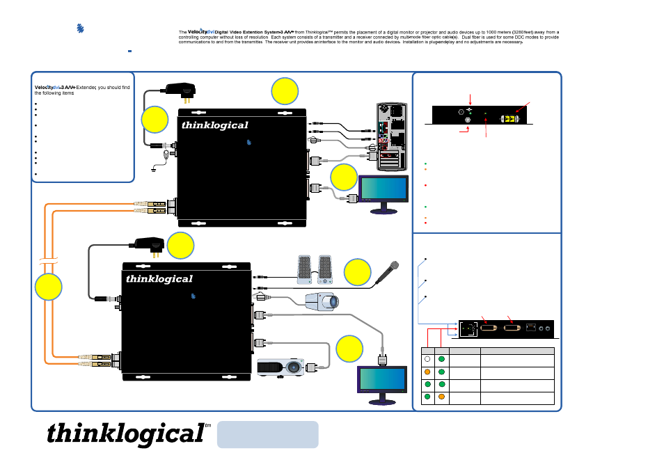
Contents
Upon receiving your Thinklogical™
DVI Extender Transmitter
DVI Extender Receiver
DVI-D Male to DVI-D Male Cable,
1 Meter (CBL-000021-001MR)
DVI-D Male to DVI-D Male Cable,
2 Meter (CBL-000009-002MR)
Two CAT5 Cables, 7' (CBL-000001-007FR)
Two 3.5mm Audio Cables
(CBL-000016-006FR)
Modem Adpt. DB9M RJ45 (ADP-000019-R)
Modem Adpt. DB9F RJ45 (ADP-000025-R)
Two Universal AC Power Adapters
(PWR-000022-R)
DVI Extender Product Manual
STEP 4
Connect your fiber optic cable,
up to 1000 meters (available
through Thinklogical™)
between the Transmitter and
Receiver Units. Do not kink or
pinch the cable and be sure to
keep all bend radii to no less
than 3 inches.
3
STEP 3
Connect the supplied AC Power
Adapter (PWR-000022-R) to the
Receiver and plug it in to a
standard AC source.
6
5
STEP 1
Connect one end of a DVI-D Male to Male Cable to the primary viewing device. Connect the
other end of the cable to the Primary (left) Receiver DVI-D connector. A second device can also
be installed to the right- side, secondary port using a similar DVI-D Male to Male cable. If using
only one device, it must be connected to the Primary Port. Turn ON the DVI video device(s).
STEP 5:
Connect the supplied AC
Power Adapter (PWR-000022-R) to
the Transmitter unit and plug it in to
a standard AC source.
Projector
Acquire Button
Used to initiate DDC collection. Works with all modes except
Pass-Thru. Must be pressed after switching between DDC
modes.
Select Button
Used to select the DDC mode. The modes will cycle through
Remote Dynamic, Remote Static, Pass-Thru and Local Static.
Both Buttons held 5 seconds
Holding both buttons for 5 seconds will reload the default DDC
table into the Tx and switch to Remote Static mode.
Fiber-optic
cable ports.
GND
Velocity
dvi
3
A/V+
OFF
GREEN
GREEN
GREEN
GREEN
GREEN
ORANGE
ORANGE
The Primary Port on the Rx is used for DDC. The Secondary
Port carries video data only.
Secondary
DVI Port
Primary DVI Port DDC
Optional Secondary DVI Port
1
Local Monitor
Power Supply
L1 L2
When lit, the solid green LED
indicates that power is applied.
Primary DVI Port DDC (Rx)
Optional Secondary DVI Port (Rx)
Transmitter
Velocity
Digital Video Extension System – 3 A/V+
MRTS
Technology
Transmitter
D
V
I
fr
o
m
C
P
U
D
V
I
to
L
o
c
a
l
D
is
p
la
y
dvi
Powered by
The Future of access and Control
tm
L2 ► Data
L1 ◄ Video/Data
L1
POWER
5 VDC
STATUS
+
_
L2
DDC MODE
LCL REM
ACQUIRE
SELECT
MIC
IN
OUT
LINE
SERIAL
Velocity
Digital Video Extension System – 3 A/V+
MRTS
Technology
Receiver
D
V
I
to
D
is
p
la
y
D
V
I
to
D
is
p
la
y
D
D
C
dvi
Powered by
The Future of access and Control
tm
L1 ► Video/Data
L2 ◄ Data
◄ Line IN
Mic OUT ►
◄ Mic IN
Line OUT ►
2
STEP 2
Connect your Mic IN, Line OUT
and CAT5 Serial devices to the
appropriate Receiver ports.
Turn the devices ON.
7
STEP 7:
Connect the Line IN and Mic OUT audio
cables and the CAT5 cable from the CPU to the
appropriate Transmitter ports. Ensure that all the
devices are turned on and all system functions are
operating properly.
CAT5
DVI-D Connect or 1
DVI -D Connector 2
STEP 6
Connect one end of the
1 meter DVI-D Male to Male
Cable (CBL-000021-001MR) to the video source
(DVI-D video card). Connect the other end to the
transmitter DVI-D connector. A local display may
also be connected using the supplied 2 meter
DVI-D Male to Male Cable (CBL-000009-002MR).
L1 to L1 and L2 to L2 Optical Fibers (up to 1000 meters)
available with ST-, SC- or LC-type connectors
VELOCITY-3AV+_Quick_Start_Rev_B