Thinklogical VX80 Velocitydvi System-3 Velocityrgb System-9 Quick Start Guide User Manual
Vx 80, Quick-start guide, Router
DDC MODE
LCL REM
ACQUIRE
SELECT
_
DDC MODE
LCL REM
ACQUIRE
SELECT
QUICK-START GUIDE
VX80 Router KVM Matrix Switch
Chassis, 6 Rack Units, 400 Watts
Copyright © 2011. All rights reserved. Printed in the U.S.A. All trademarks and service marks are the property of their respective owners.
Visit us online at
www.thinklogical.com
for more product information, current updates and the complete line of Thinklogical
®
products.
Single-Head DVI Source
KVM Matrix Switch
Powered by
MRTS
Technology
RGB IN
Single Head RGB/Audio Source
Velocity
VEL-AV0M09-LCTX
RGB, Audio, Serial
TRANSMITTER
VGA 1 (PRIMARY)
VGA 2 (SECONDARY)
Audio OUT►
Single-Head DVI Destination
VX
80
router
QUICK-START GUIDE
3
STEP 3:
Depending on your
desired configuration, connect your
video devices to the
VelocityDVI-3
Receiver using DVI cables. Turn
all the devices ON.
Power Supply
(PWR-000022-R)
Power Supply
(PWR-000022-R)
STEP 3:
Connect your output devices (monitors, audio
speakers, projector, etc.) to the
VelocityRGB Receiver
using standard cables. Turn all the devices ON.
7
STEP 7: Connect your Audio cables
to the
VelocityRGB Transmitter’s
LINE IN and MIC OUT ports.
STEP 7:
If desired, connect a local video device
to the Transmitter’s
DVI to Local Display port.
STEP 1:
Connect your
VelocityRGB
Receiver to the
VX
80
using multi-
mode fiber-optic cables (up to 1000
meters). Connect
L1
to any Transmit
Port and
L2
to any Receive Port. (See
the Digital Crosspoint Switch detail
diagram, left.)
STEP 6:
Connect the RGB IN cable from the
CPU to the
VelocityRGB Transmitter and
the Local Display Cable from the Transmitter
to your local monitor.
STEP 9: Connect both supplied AC Power Cords (PWR-0000006-R) to the
receptacles located on the
VX
80
's power supplies. Plug each of them into a
standard AC source. Verify that all system functions are operating properly.
L1
L2
L1
L2
5
STEP 5:
Connect the 5VDC
Power Supply and plug it into
a standard AC source.
1
AUDIO►
▲
▼
▲
▼
2
9
STEP 8: Connect the Controller
Cards’ LAN Ports to your
Control CPU with CAT5 cables.
8
L2
L1
POWER SUPPLY 1 (LEFT):
POWER SUPPLY 2 (RIGHT):
FANS:
TEMPERATURE WARNING:
TEMPERATURE SHUTDOWN:
CPU:
INPUT/OUTPUT CARDS:
ANY OF THE ABOVE
COMMON
GROUND
The
VX
80 Router
Critical Hardware Alarms:
(Located at the top, left rear of the unit.)
Fan failure, temperature spikes, DC voltage and/or current out of range, AC power input interruption and module removed
Fan failure, temperature spikes, DC voltage and/or current out of range, AC power input interruption and module removed
Individual fan monitoring
Chassis over temperature, multiple sensors
Chassis over temperature causing shutdown
Card failure (Only with a redundant card)
SFP+ failure, laser output fault
SERIAL PORT
+
_
5VDC
L1
L2
FIBER
TO LOCAL
DISPLAY
FROM CPU
LOS
LINE IN
MIC OUT
DOWNLOAD
POWER
CNTRL
SERIAL PORT
+
_
5VDC
L2
L1
FIBER
VGA 2
VGA 1
LOS
LINE OUT
MIC IN
DOWNLOAD
POWER
CNTRL
rgb
VEL-AV0M09-LCRX
RGB, Audio, Serial
RECEIVER
Velocity
rgb
Thinklogical’s™
VX
80
KVM Matrix Switch features redundant
Power Supplies and Controller Modules for uninterrupted
performance, even during system reconfiguration, updates or
debug. The
VX
80
remains fully functional with only one Power
Supply installed or with one Controller activated.
NOTE:
When using a single Controller, the module on the left
(Primary) must be used.
◄AUDIO
6
◄AUDIO IN
VX80_VEL-3_VEL-9_QSG_Rev_B
DVI from CPU
DVI to Local Display
Power Supply
(PWR-000022-R)
DVI to Display DDC DVI to Display
Power Supply
(PWR-000022-R)
PROJECTOR
(Primary DDC Port)
STEP 2:
Connect
the 5VDC Power
Supply and plug it
into a standard AC
source.
Digital Video Extension System-3 RECEIVER
RGB Video & Audio
Destinations
2
STEP 2:
Connect the
5VDC Power Supply
and plug it into a
standard AC source.
Velocity
dvi
Digital Video Extension System-3 TRANSMITTER
6
STEP 6:
Connect your DVI cable from the Source
CPU to the
DVI from CPU Transmitter port.
5
STEP 5:
Connect the 5VDC
Power Supply and plug it into
a standard AC source.
DVI Out from CPU
CPU IP address:
192.168.13.9
Velocity
dvi
Powered by
MRTS
Technology
Powered by
MRTS
Technology
Powered by
MRTS
Technology
Powered by
MRTS
Technology
As used with Thinklogical’s
®
Velocity
dvi Video Extension System-3
and the
Velocity
rgb Video Extension System-9
4
L2
L1
*
*
VEL-000M03-LCTX
VEL-000M03-LCRX
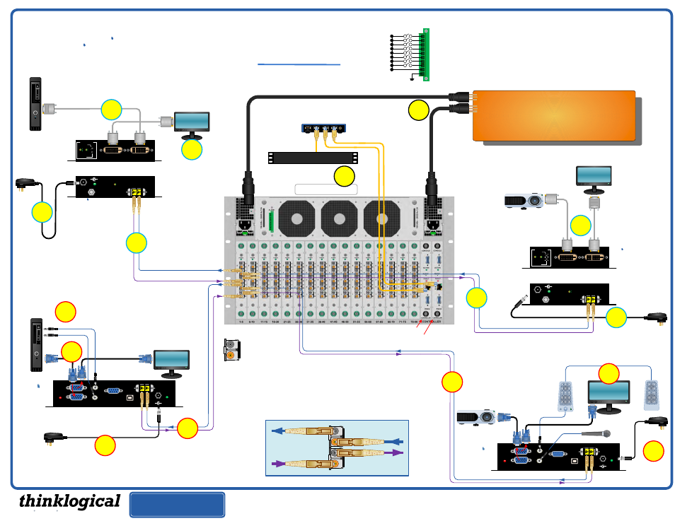
Complete steps 1 through 9 to connect your Thinklogical™
Velocity-3 DVI
and your
Velocity-9 RGB Fiber-Optic Video
Extension Systems
through the
VX80 KVM Matrix Switch
.
Follow the same steps to connect any additional devices.
Refer to the Digital Crosspoint Switch diagram below to
help you determine where to connect your fibers.
1
2
3
4
5
6
7
8
9
10
Network Hub
External Control CPU
PHONE: 1-800-291-3211
WEBSITE: www.thinklogical.com
EMAIL: [email protected]
L1
4
7
Local DVI
(optional)
STEP 4:
Connect your
VelocityDVI-3 Transmitter to the
VX
80
using multi-mode fiber-optic
cables (up to 1000 meters).
Connect
L1
to the Receive Port on
the same SFP as the DVI
Receiver’s L1 fiber and connect
L2
to the Transmit Port on the same
SFP as the DVI Receiver’s L2
fiber. (See the Digital Crosspoint
Switch detail diagram, below.)
STEP 4:
Connect your
VelocityRGB Transmitter to
the
VX
80
using multi-mode fiber-optic cables (up to
1000 meters). Connect cable
L1
to the Receive Port
on the same SFP as the RGB Receiver’s L1 fiber and
connect cable
L2
to the Transmit Port on the same
SFP as the RGB Receiver’s L2 fiber. (See the Digital
Crosspoint Switch detail diagram, right.)
Local RGB
Display
Optional
Secondary DVI
Port
L2
L1
L2
VGA 2
3
L1: Video and Data Tx to Rx
L2: Data Rx to Tx
POWER
5VDC
STATUS
+
L2
L1
POWER
5VDC
STATUS
+
_
L1
L2
Primary Controller Card
(IP address: 192:168:13:15)
Optional Secondary Controller Card
(IP address: 192:168:13:16)
1
STEP 1:
Connect your
VelocityDVI-3
Receiver to the
VX
80
using multi-
mode fiber-optic cables (up to 1000
meters). Connect
L1
to any SFP’s
Transmit Port and
L2
to any SFP’s
Receive Port. (See the Digital
Crosspoint Switch detail diagram,
below.)
To SFP Receive port
Data Rx to Tx
From SFP Transmit Port
Data Rx to Tx
To SFP Receive Port
Data Tx to Rx & Video
From SFP Transmit Port
Data Tx to Rx & Video
SFP Module
Transmit Port (output)
Receive Port (input)
Extend Distribute Innovate
®