Triplett POE1000IL/POE1000ILT User Manual
Power panel, User’s guide, Inline cat5/6 dvm and poe tester + tone
POWER PANEL
POWER PANEL
TM
USER’S GUIDE
WATCH ALERT LEDS. They light if a
network device is ON or if a phone or PoE voltage
is present.
POWER ON: Press any button.
POWER OFF: Press and hold the SEL (select) button until off.
BATTERY SAVER: No activity for 5 minutes shuts the Power Panel OFF.
C
D
V
BAT
7
6
5
4
3
2
1
8
INTERACTIVE BUTTONS
Simulates a Power
over Ethernet (PoE)
device, prompting full
PoE voltage.
See page 5.
Press to prompt
devices to talk to
you. Hold for 5
secs to turn on
Port
Beacon. See page 4.
INLINE CAT5/6 DVM AND PoE TESTER + TONE
Use the SEL button to select between displays.
Note: Display is available only if LED is lighted.
SELECT A LCD DISPLAY. Each lighted LED has
a corresponding LCD display with information. Use
the SEL button to move between displays.
Go to www.bytebrothers.com
for more information about the Power Panel CAT5/6 DVM.
NETWORK LED. See page 4.
POWER LED. See page 5.
PHONE LED. See page 6.
CONNECT THE POWER PANEL: Connect the tester either directly
to the device you wish to test (use center jack) or connect it inline (in between)
two devices (inline is used for network monitoring and measuring PoE power).
Follow these 4 steps to use the Network Power Panel.
To trace cables or ports with the Locator Tone or Locator Port Beacon,
see Interactive buttons at the bottom of the page.
Turns Power Panel ON
and OFF. Selects LCD
displays. After tester is
ON, hold for 4 secs to
turn on
Locator Tone.
LOCATOR TONE, PORT BEACON, FORCE LINK, TEST PoE
NETWORK
C
D
V
8
7
6
5
4
3
2
1
THE NETWORK POWER PANEL IS AN INSTALLERS BEST FRIEND!
Watch the numbers. You can see
which pair it is studying:
1,2....3,6....4,5....7,8.
LAN devices, phones, PoE (voltages)
are all displayed. “1” through “8” refer
to the pin numbers of jack or cable
connected to the Network Power Panel.
See below for a typical cable diagram.
3 ultrabright LEDs are the first
alert of activity or voltage!
1. Locate the active devices and voltage on the Ethernet cable (or port)
2. Display the speed (10/100/1000), duplex and pinouts of the devices
3. Display the PoE voltage and pinouts (if PoE is present)
The Network Power Panel can plug into any device with an Ethernet plug... such as a
computer, switch, VoIP phone, IP camera, or access point... ... the
Network Power Panel works with them all.
During the install or repair of a network device, use the Power Panel:
1. Display the negotiated speed (10/100/1000) of the devices when connected
2. Measure the power usage (in watts) of the PoE device
Once your installion is complete, use the Power Panel to:
Ethernet: The network devices and cabling connecting computer devices is called “Ethernet”.
Ethernet cables, with few exceptions, are all the same: They are constructed of 4 twisted
pairs of copper wire and connected in the following pattern to the connector pins 1-8 (the
twisted pairs are connected to pins 1/2 3/6 4/5 and 7/8).
EIA/TIA 568B
STRAIGHT THRU CABLE
(MOST POPULAR)
GENERAL INSTRUCTIONS
THE 4 STEPS TO USING THE NETWORK POWER PANEL
QUICK START GUIDE
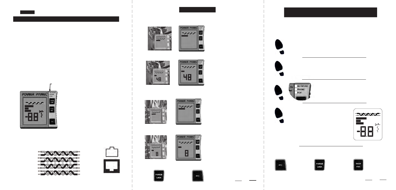
DETERMINE SPEED OF SWITCH: Connect the tester directly
to the switch port you wish to test (use either Power Panel jack).
DETERMINE IF SWITCH HAS POE CAPABILITY: Connect as in above example.
DETERMINE THE POWER DRAW OF THE CONNECTED DEVICE: Connect inline.
LOCATE A CABLE END WITH EITHER THE PORT BEACON OR TONE:
The NETWORK LED is lit. Press SEL
to go to the NETWORK screen. The display
says the device is transmitting on pair 3,6.
The speed and duplex are indicated
(10,100,1000,HD,FD). A “Force
Link” button coerces a dialog.
The POE LED is lit. Press SEL to go
to the PoE screen. A PoE “end span”
voltage of 48V is on pairs 1/2 & 3/6. If a
lower “discovery” voltage is displayed,
press “PoE Test” to simulate a PoE
device and prompt the full 48VDC of PoE.
Hold for 5
secs to turn on
Port Beacon.
See page 4.
Turns Power Panel ON
and OFF. Selects LCD
displays. After tester is
ON, hold for 4 secs to
turn on
Locator Tone.
The POE LED is lit. Press SEL to go
to the PoE screen. As in the above
screen, the PoE voltage is on pairs 1/2
& 3/6. Watch the large digits. The first
displayed is the PoE power draw in watts
(8 watts shown). The second is the DC
voltage amplitude (typically 48 VDC).
3
2
PoE: Power supplied to network devices over a CAT5/6 cable. See the bottom of page 5.
D
I
M
D
N
E
E
O
P
E
N
O
H
P
0
1
0
0
D
F
D
H
T
E
N
R
O
W
K
W
W
1
2
3
6
4
5
7
8
1
2
3
6
4
5
7
8
Orange/White
Orange
Green/White
Green
Blue
Blue/White
Brown/White
Brown
0
1
NETWORK
0
0
D
F
D
H
6
3
C
D
V
D
N
E
E
O
P
6
3
2
1
C
D
V
D
N
E
E
O
P
6
3
2
1
0
1
NETWORK
0
0
D
F
D
H
6
3
D
N
E
E
O
P
6
3
2
1
D
N
E
E
O
P
6
3
2
1
DETERMINE THE NEGOTIATED SPEED OF TWO DEVICES: Connect the tester
inline (in between) two devices (example: between the VoIP phone and switch).
6
3
2
1
6
3
2
1
When connected together, any 2 network
devices negotiate a speed. The inline
Network Power Panel goes in between
the 2 devices and displays the result. In
this case, it’s 100MB/s, full duplex on pairs
1/2 & 3/6.
1 2 3 4 5 6 7 8
RJ45 SOCKET/PLUG
PIN DIAGRAM
0
1
NETWORK
0
0
D
F
D
H
0
1
NETWORK
0
0
D
F
D
H
D
I
M
D
N
E
E
O
P
E
N
O
H
P
0
1 0
0
D
F
D
H
T
E
N
R
O
W
K
W
W
①
②
③
④