0 introduction, Able of, Ontents – Verilink 210 (34-00196) Product Manual User Manual
Page 3: Peration
T
ABLE OF
C
ONTENTS
General
Introduction ................................................................................... 4
Specifications ................................................................................ 5
FCC Requirements ........................................................................ 6
Warranty ........................................................................................ 7
Ordering Numbers ......................................................................... 8
Installation
Introduction ................................................................................... 9
Supplied Materials ........................................................................ 9
Unit Configuration ........................................................................ 9
Configuration Switch S1 ........................................................ 10
Configuration Switch S2 ........................................................ 11
Connections ................................................................................... 12
DTE and Network Connections ............................................. 13
Power Connection .................................................................. 13
Operation
Introduction ................................................................................... 14
Testing ........................................................................................... 15
TxPORT Customer Service .......................................................... 16
3
14
O
PERATION
3.0
Introduction
This chapter describes the front panel operation and test features of the TxPORT 200
and 210 CSUs. Both units are controlled manually using a front panel test switch and
rear panel DIP switches (the DIP switches are discussed in the ‘Installation’ chapter).
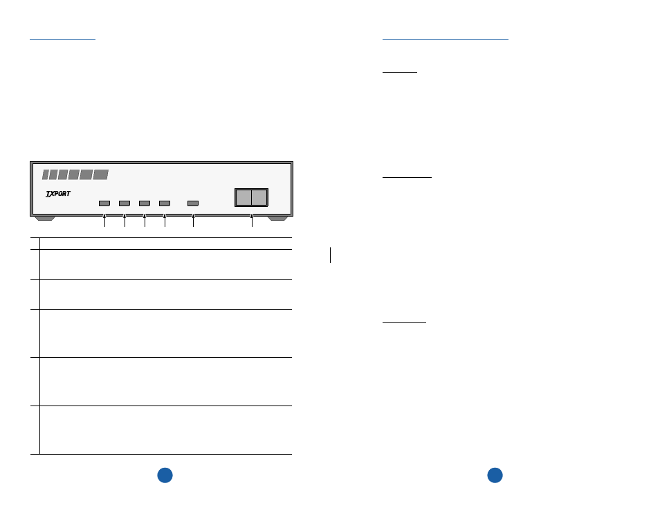
The front panel switch and the LED indicators are described below.
LOOP
NORM
CSU
PWR
DTE
NET
LOOP
FAR
PRODUCTIVITY
SERIES
200
200 CSU Front Panel
T
R
A
N
S
P
O
R
T
®
1 POWER: This green LED lights when power is applied to the unit.
2 DTE T1 Status: This red LED lights if the internal alarm circuitry detects a loss
of signal condition for Š 175 bit times from the DTE. The LED stays lit until the
unit detects Š 4 pulses in 32 bit times.
3 Network T1 Status: This red LED lights if the internal alarm circuitry detects a
loss of signal condition for Š 175 bit times from the network. The LED stays lit
until the unit detects Š 4 pulses in 32 bit times.
4 Far end T1 status (200 CSU only): This red LED lights if the internal alarm cir-
cuitry detects a yellow alarm signal from the far end terminal equipment. This con-
dition occurs if the far end terminal is out of sync with the T1 signal from the
network. The format for a yellow alarm is bit 2 set to 0 in each DS0 (D4 mode) or
8 ones /8 zeros in the facility data link (ESF mode).
5 Loop: This amber LED lights under the following conditions: the manual loop
switch is placed in the ‘LOOP’ position or the unit receives an inband loop code
for > 5 seconds, or (for the 200 only) the unit receives an FDL loop message (PLB
or LLB). The LED does not light if the test switch is placed in the ‘NORM’ posi-
tion or if an inband or FDL unloop code is received for >5 seconds.
6 Test Switch: This 2-position switch is used for local testing. When placed in the
local loop mode (LOOP), the unit loops the signal from the customer equipment
(DTE IN) back to the customer equipment (DTE OUT). It also loops the received
signal from the T1 facility (NET IN) back to the T1 facility (NET OUT). When
moved back to ‘NORM’, the local loopback is removed.
6
5
4
3
2
1