5 unit configuration – Verilink 2048 (34-00179) Product Manual User Manual
Page 9
2-2
Installation
2048 PMU/NTU
-15
-7.5
0
The stand-alone unit may be used in a chassis installation
with the following modifications: Remove the housing as
described above and then remove the four screws holding
the front panel to the circuit boards. Replace the stand-alone
front panel with a module type front panel. The unit will
now slide into one of the 12 slots in the chassis.
2.4.2
Chassis Assembly
Up to 12 units may be inserted into a chassis and the chassis
may be installed in a 19" or 23" rack using four screws.
Connections are made from the rear of the chassis. Refer to
the figures on page 2 -10 for these illustrations.
2.5
Unit Configuration
The 2048 PMU model is designed as a two card set. The
two cards roughly divide into analog and digital functions.
The unit provides an interface to the network in compliance
with established standards. It has been designed to operate
either manually or through the use of a console/terminal.
Therefore, the unit has both hardware and software configu-
ration settings.
This following paragraphs explain the various hardware
configurations that may be adjusted for unique applications.
Software controlled settings are discussed in the Operations
section of this manual.
2.5.1
Switch SW1 (BERT Pattern)
When the PMU is instructed to send a test pattern by the test
switch (FAR /LOC) on the front panel, it will send 5 seconds
of inband loop code (10000) and then transmit the test pat-
tern as determined by rotary switch SW1 (refer to the fol-
lowing table). This switch is located on the front panel
(shown on page 3-1).
PROM Downloading Procedures: Rotary switch SW1,
position 9 is used to download new PMU operating firm-
ware into the flash memory. This operation requires a PC
and a diskette which contains TxPORT’s downloading pro-
gram (
download.exe
) and the hex file to be downloaded.
Downloading procedures are described in the 2048 Down-
load Procedures document sent with the software.
2.5.2
Switch SW2 (National Bit)
Rotary switch SW2 is used to select the National Bit. The
following table shows the switch positions. The factory
default is position 1.
Switch S6 has two positions affecting the options for Switch
SW2. For position S6-7, Down = ‘Pass’ and Up = ‘Select’.
For position S6 -8, select either ‘Down’ (0) or ‘Up’ (1) for
National Bit data (applies only if position S6-7 is set for
‘Select’). Switch S6 is covered in Section 2.5.7 on page 2-4.
2.5.3
Switch S1 (Network LBO)
The output signal level of the transmit data (TXD) from the
2048 PMU to the network must be set by the LBO switch
Pos
0
1
2
3
4
5
6
7
9
Pattern QRW 2
7
2
9
2
15
2
20
2
23
1:8 3:24 PROM
Pos
0
1
2
3
4
5
6
7
8
9
NB
N /A
1
2
3
4
5
4
4
4
4
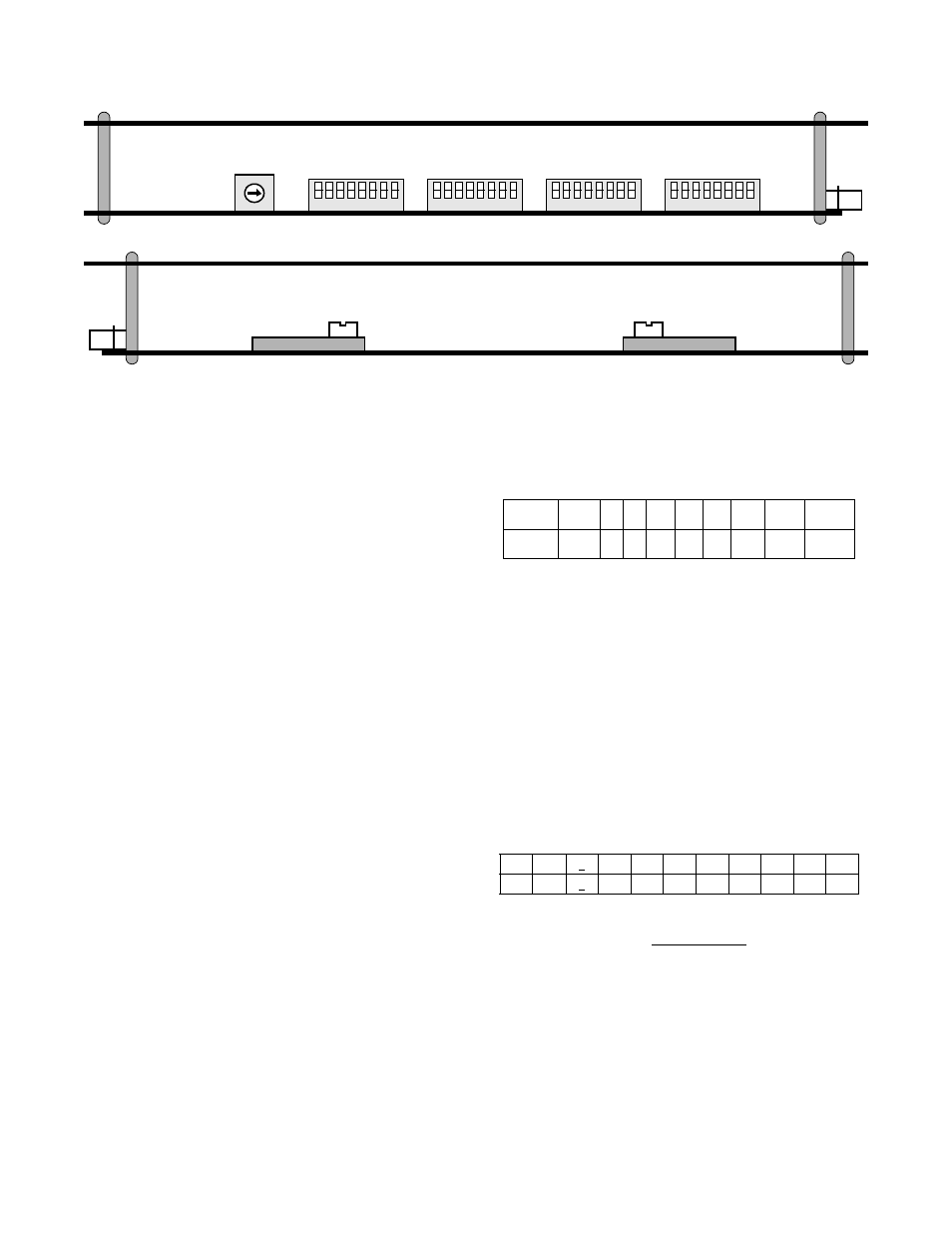
Figure 2 -1
Circuit Board Views
1 2 3 4 5 6 7
Switch S7
8
1 2 3 4 5 6 7 8
1 2 3 4 5 6 7 8
1 2 3 4 5 6 7 8
0
6
2
4
5
1
3
7
8
9
Switch S6
Switch S5
Switch S4
Switch SW2
2048
rear
2048
rear
Switch S1
Switch S2
NORM
RACK