Prism 3000 – Verilink PRISM 3000 (34-00184) Product Manual User Manual
Page 22
PRISM 3000
3-6
Operation
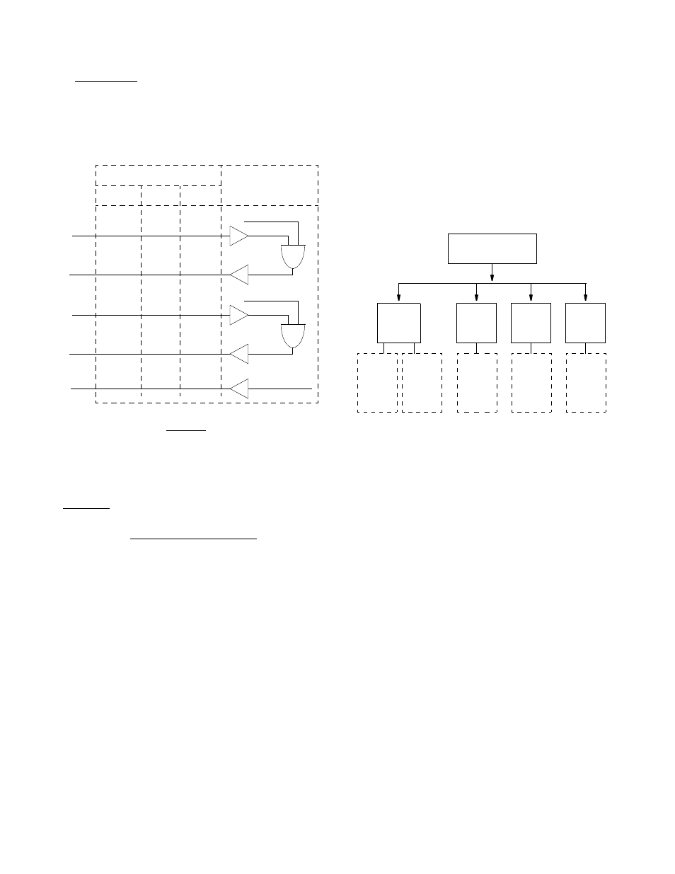
CTS /DSR/DCD Control: Setting any of these three fields
to ‘
FORCE
TRUE
’ or ‘
FORCE
FALSE
’ allows the forcing of
the port control lead output state. ‘
INTERNAL
’ allows for
normal operation as shown in the diagram of the ‘High
Speed Data Port’
below
.
High Speed Data Port
V.54 Loop: Selecting ‘
Enable
’ allows the unit to respond
to inband V.54 loop commands. If ‘
Disable
’ is selected,
the unit ignores these commands.
Alarm on DTR Loss: Selecting ‘
Enable
’ allows the
PRISM to alarm on loss of DTR. The default setting is
‘
Disable
’.
EIA530 or RS232 Option
The RS232 low speed port option is available as a combina-
tion board with an EIA530 or V.35 port. The RS232 port
provides a synchronous DCE interface at subrate speeds for
connection to customer DTE. The data from the port is
placed in a single selected DS0 channel of the T1 network
data stream. For switched carrier applications, the RS232
port provides local RTS to remote DCD control lead opera-
tion at all speeds below 64 kb/s.
The RS232 port provides a bidirectional loop for isolating
problems associated with the interface. Looping the port
does not affect data traffic assigned to any of the other DTE
ports. The port loop may be activated from the front panel,
the terminal interface, the EM8000, Telnet across the Ether-
net or Token Ring interface, or by the reception of inband
V.54 loop code. The unit can also be instructed to transmit
the inband V.54 loop code to loop the corresponding remote
end port.
The PRISM has an internal BERT tester with ten available
stress patterns. The user may utilize this capability by loop-
ing one end of the DS0 channel assigned to the RS232 port
and BERT toward it from the other end. RS232 BERT is
valid only at 56kb/s and 64kb/s toward the DTE.
The following RS232 menu diagram is an addition to the
‘DTE Port Configuration’ menu diagram. It shows the mod-
ified menu options available for the RS232 port. The differ-
ences are explained in the following paragraphs.Note that
only Port 1 and Port 3 are available for the RS232 option.
RS232 Modifications to DTE Port Menu
Port Rate: This parameter selects the required port bit rate
for RS232 operation. The ‘
None
’ option disables all opera-
tions for this port.
DS0 Channel Assignment: ‘
CONTIGUOUS
’ is the only
option available for RS232 operation.
CTS/DSR/DCD Control: The control leads on the RS232
port function as explained in the following paragraphs.
DSR Control: May be set to ‘
Force
True
’, ‘
Force
False
’, or ‘
Internal
’. The ‘
Internal
’ option has
DSR ON if the port is enabled and OFF if it is disabled.
DCD Control: May be set to ‘
Force
True
’ or ‘
Inter-
nal
’. If set to ‘
Internal
’, DCD is ON when data is
being received from the remote end and is OFF when idle
code is being received from the far end. Setting to ‘
Force
True
’ keeps DCD ON regardless of whether data or idle
code is being received.
CTS Control: May be set to ‘
Force
True
’ or ‘
Inter-
nal
’. The setting of CTS Control has an effect on both the
CTS control lead presented to the DTE and on the transmit
data from the DTE toward the remote end.
If set to ‘
Internal
’ the CTS control lead will follow the
RTS control lead from the DTE after a delay of 21 UI (± 1
UI). The data transmitted to the remote end will also be
determined by the state of the RTS control lead. When RTS
DCD
EIA530
V.35
RS449
12/ 30
H
20/23
4/19
5/13
6/22
8/10
F
13/31
E
11/29
D
9/27
C
7/25
AND
T1 Receiver In Sync
T1 Loss Of Signal
Connector Pin Numbers
PRISM
3000
DTR
RTS
CTS
DSR
Alarm State
AND
Port Enabled
Port 1 / Port 3
Configuration Menu
Port
Rate
DS0
Channel
Assign.
CTS
Control
DCD
Control
None
1200 bps
2400 bps
4800 bps
9600 bps
14400 bps
Contiguous
Internal
Force
True
Internal
Force
True
19200 bps
28800 bps
38400 bps
48000 bps
56000 bps
64000 bps