Verilink 1251 (CG) Configuration/Installation Guide User Manual
1251 power maintenance card, Configuration guide, General
1
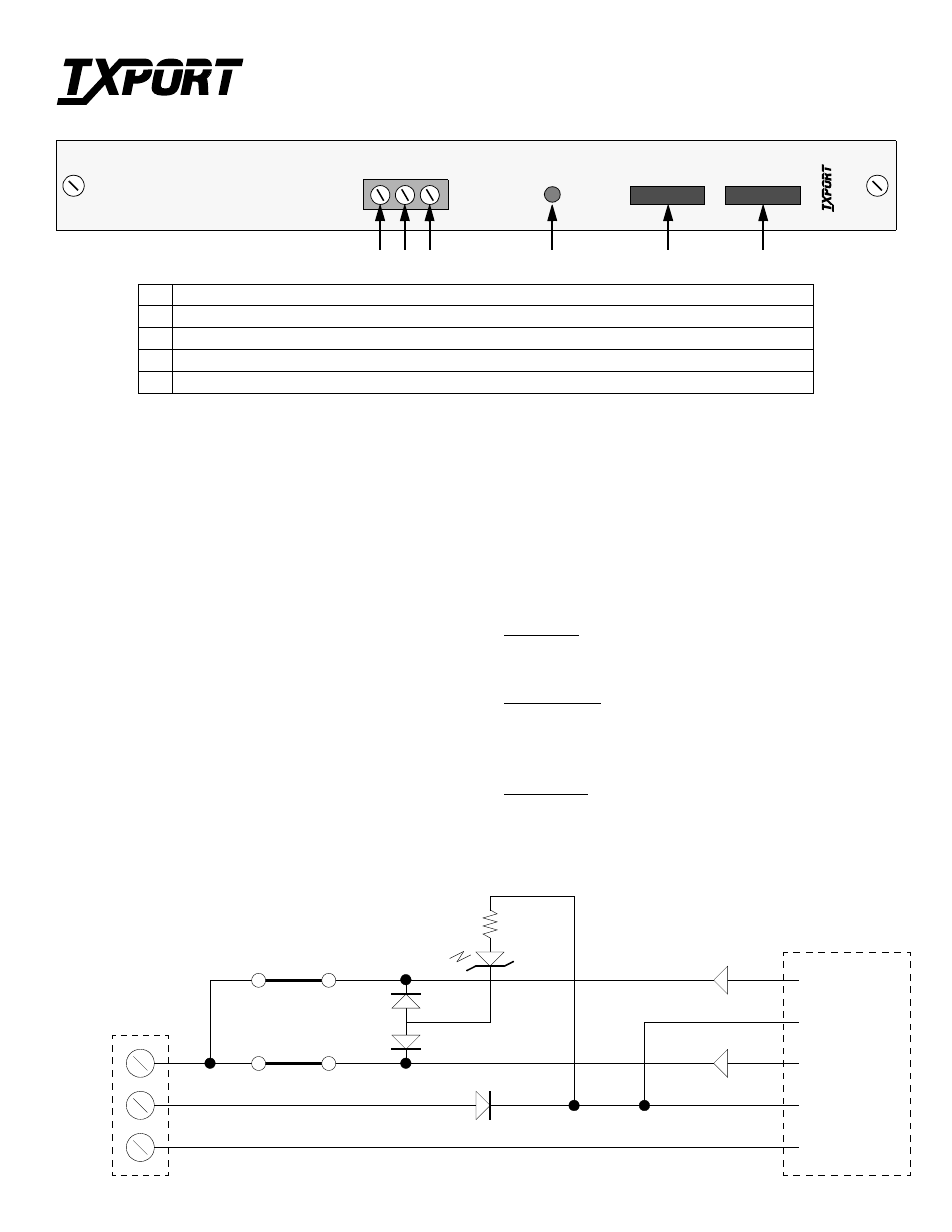
-48 Volts: This terminal screw connects to a -48 Volt DC power source.
2
Return: This terminal screw connects to the power source return.
3
Ground: This terminal screw connects the card to the chassis ground.
4
Power: This green LED indicator is ON when -48 VDC power is being supplied to the unit.
5
3 Amp GMT Fuse: These two fuses (F1 and F2) protect the 1251 card from input power shorts.
T
R
A
N
S
P
O
R
T
®
PO
WE
R
MAI
N
T
PWR
3 Am
p
GM
T
12
51
TRANSPORT
®
CARD
-4
8
RT
N
GND
1
2
3
4
5
5
General
The 1251 Power Maintenance Card is designed to provide temporary
power to a 1555 APC chassis during shelf maintenance periods which
involve the removal or replacement of the Power and Alarm card.
Caution: The 1251 card is not mechanically or electrically com-
patible with the Power and Alarm card slot. Do not insert this card
into Slot 1.
The 1251 front panel contains a screw terminal strip with 3 connectors,
two GMT type power fuses, a power LED indicator, and two card-
retaining thumb screws.
Design Features
• The card may be installed in any vacant 1557 APC card slot.
• The card is compatible with any 1555 APC chassis.
• The card provides fused input protection and a power indicator.
Operation
Refer to the front panel diagram above and to the simplified circuit dia-
gram below for the following operational features.
An external -48 VDC fused source is fed into the card from the front
panel screw terminal strip. This power is then fed through front panel
card fuses F1 and F2 (GMT type, 3 Amps). The power is then fed to
both the A and B power bus pins of the card connector. Both A and B
feeds are diode protected from power reversals.
The front panel power indicator is diode biased to allow the LED to be
on only when the proper polarity of -VDC is wired to the front panel
terminal connections.
Specifications
Mechanical
Dimensions:
10.5" H, 1" W, and 11" D
Weight:
approximately 10 ounces
Environmental
Operating Temp:
0
°
to 50
°
C (32
°
to 122
°
F)
Storage Temp:
-20
°
to 85
°
C (-4
°
to 185
°
F)
Humidity:
95% max (non-condensing)
Part Number
F-1251-001--11
Chassis Ground
Return (B)
-48 VDC (B)
Return (A)
-48 VDC (A)
Fuse F2
Ground
Return
-48 VDC
Simplified Circuit Diagram
Power
Card
Fuse F1
Power
Terminal
Diode
Isolation
Connector
Power/Polarity
ON Indicator
1251 Power Maintenance Card
Configuration Guide
Part Number 45-00062
Rev 1.00