Verilink 1558D (CG) Configuration/Installation Guide User Manual
1558d aps, Configuration guide, Txport 1558d
1558D APS
Configuration Guide
Part Number 45-00102
Revision 1.0
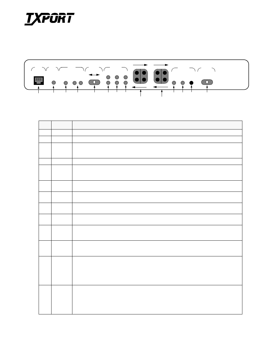
1558D Front View
1558D Controls and Indicators
Index
Indicator
Description
1
SUPV
The Supervisory port allows the user to connect to the 1558D via a PC running the supplied LAPS software.
2
Power
The power (green) LED will be ON when a nominal power source of 110 volts AC is present.
3
Locked
When the Locked amber LED is on, the 1558D has been manually or remotely (soft control) forced and locked to
either the A or B path. Moving the Path Select switch back to the AUTO position or remotely sending an unlock com-
mand will turn off this LED and restores normal APS operation.
4
A / B
These green status LEDs indicate which of the two T1 receive paths (A or B) is presently actively carrying the service
5
Path Select
Auto /A/B
The user can manually force and lock either the A or B path as the active path by moving this switch from the AUTO
position to either the A or B position. The 1558D is now manually locked to this path and will not switch from it, even
if the selected path fails
6 Alarm
A/B
When on, these red LEDs indicate that one or more of the user definable alarm parameters (ES, CSES, LOS, and LOF)
have been met or exceeded for Path A or Path B, respectively.
7
LOS
When on, these red LEDs indicate that no T1 pulses are being detected on the receive signal paths from the network
for Path A or Path B, respectively.
8 Loop
A/B
When on, these amber LED indicates that a loop (either manually or under soft control) has been activated for Path A
or Path B, respectively.
9/10
Test Jacks
Bantam test access jacks and bridge/monitor jacks are provided to gain physical test access to the T1 path for NET A,
NET B, and the T1 DTE transmit and receive signal paths (see 1558D Block Diagram).
11
Send Data
This green LED will indicate that data transitions are present on the Send Data (to the network) lead coming from the
DTE equipment. The LED will be on for a mark condition and off for a space condition. The LED will vary in intensity
depending upon the relative number of marks or spaces present at any given time.
12 Receive
Data
This green LED will indicate that data transitions are present on the Receive Data lead coming from the active network
path (A or B). The LED will be on for a mark condition and off for a space condition. The LED will vary in intensity
depending upon the relative number of marks or spaces present at any given time.
13
Test
This LED (tri-colored amber, red, green) will indicate when the DSU portion of the 1558D has been placed in a test
mode either via remote commands or activation of the front panel loop switch. The LED will be ON (amber) when
the manual switch is placed in the local loop position or when a remote equipment or V.54 loop command has been
received. Initially, the LED will be on (amber) when the manual loop switch is placed in the Remote Loop (V.54)
position. After activation, the LED will turn from yellow to red if the unit does not detect a far end V.54 loop. If a loop
is detected from the far end, the LED will change from amber to green (far unit in loop).
14
Loop
Switch
This three position loop switch (Remote Loop, Normal, Local Loop) allows the user to initiate a LL (local loop) or a
far end 1558D RL (remote V.54 loop). Moving the switch to the LL (local loop) position initiates a loop of both the
A and B paths back to the 1558D unit (see 1558D Block Diagram). Placing the switch in the RL position initiates a
V.54 inband loop command towards the far end unit. A V.54 loop initiates an an Equipment Loop of the far end unit
(see 1558D Block Diagram. Moving the switch back to the Normal position removes the loop condition (either local
or remote). The Remote loop/unloop process takes approximately 5 seconds to complete.
1
2
3
4
5
6
7
8
9
10
11
12
13
SUPV
STATUS
A
LOCKED
B
A
B
ALM
LOS
LP
A
SELECT
AUTO
PATH
B
STATUS
PATH
RX BRDG
TX BRDG
N
E
T
A
RX BRDG
TX BRDG
N
E
T
B
SD
RD
TEST
STATUS
DTE
NORM
LOOP
LL
RL
PWR
14
TxPORT
1558D
T
R
A
N
S
P
O
R
T
®