Installation instructions – WattMaster WCC III part 18 User Manual
Page 3
WCC III Technical Guide
17. Binary Input w/Time Delay Board Installation
17-1
Installation Instructions
SAT II controller.
The eight Binary Inputs on the new WCC3 Binary Input /w time delay board are dry contact closures to ground only.
stay on after a momentary switch contact is applied to the input of the new WCC3 Binary Input /w time delay Board.
With the time delay dipswitch (1 to 4) all OFF, there is no delay ON for all eight inputs.
Time Delay dipswitch # 1 - (15 MIN) ON there is a 15 minute delay ON for all eight inputs.
Time Delay dipswitch # 2 - (30 MIN) ON there is a
1
2
hour delay ON for all eight inputs.
Time Delay dipswitch # 3 - (1 HOUR) ON there is a 1 hour delay ON for all eight inputs.
Time Delay dipswitch # 4 - (2 HOUR) ON there is a 2 hour delay ON for all eight inputs.
Time Delay dipswitch # 5 - (3 HOUR) ON there is a 3 hour delay ON for all eight inputs.
Time Delay dipswitch # 6 - (4 HOUR) ON there is a 4 hour delay ON for all eight inputs.
These Dipswitch settings are additive. With Time Delay dipswitch (1 - 15 MIN, 2 - 30 MIN, and 3 - 1 HOUR) ON there is a 1 hour and 45 minute delay
ON for all eight inputs. The eight LEDs marked BIN1 to BIN8 follow the Time Delay set by the Time Delay dipswitch #1 to # 6.
time delay board via a PCC cable.
time delay board via a PCC cable.
You should never have both Time Delay dipswitch #7 & #8 ON at the same time. One or the other but not both.
Note:
Communications to the WCC3 Binary Input /w time delay board via the SAT III Controller's HSS communications port. The HSS connects are meant to
be daisy chained with each HSS expansion board having two HSS connectors on it.
There are 16 independent time delays on the Binary Input screen of the WCC III front end software. One for each of the 16 binary inputs.
The eight input status LEDs on the new WCC3 Binary Input /w time delay board also do not work during a time delay when it is connected to the SAT
III via the HSS port.
This Binary Input board power requirements are 24VAC and it draws 5 VA.
for this power connection to the SAT III controller.
When ordering the WCC3 Binary Input /w time delay board you must specify the length of the HSS cable at the time of the order
The cables below are also available for order:
PCC-01 (Power and Communications Cable - 1 foot long)
PCC-1.5 (Power and Communications Cable -
1
2
)
foot long
PCC-25 (Power and Communications Cable - 25 feet long)
PCC-40 (Power and Communications Cable - 40 feet long)
PCC-80 (Power and Communications Cable - 80 feet long)
PCC-120 (Power and Communications Cable - 120 feet long)
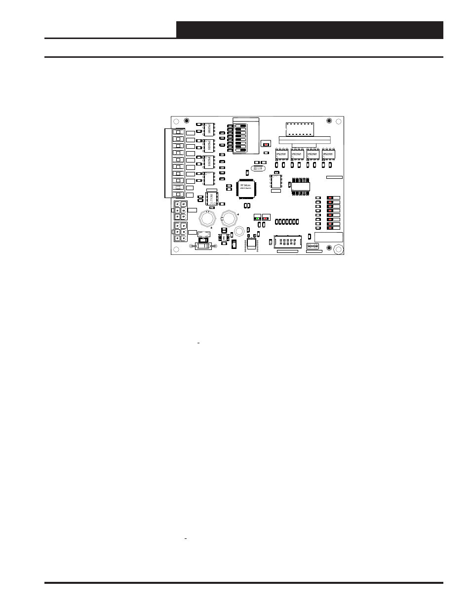
ENGINEERING INSTALLATION GUIDE
WCC3 HSS BINARY INPUT WITH TIME DELAY BOARD
WATTMASTER PART # OE431-01 (SS5006)
COMM
GND
GND
BIN8
BIN7
BIN6
BIN5
BIN4
BIN3
BIN2
BIN1
BIN1
BIN2
BIN3
BIN4
BIN5
BIN6
BIN7
BIN8
MADE IN USA
SERIAL #
15 MIN
30 MIN
1 HR
2 HRS
3 HRS
4 HRS
L1-8
L9-16
TIME DELAY
HSS
HSS
EEPROM
485 DRV
POWER
PROGRAM SOCKET
STAT
CHASSIS GND
U14
C1
6
C1
5
R48
X1
V1
U13
U1
2
U11
U9
U7
U6
U4
U3
U2
U1
TB1
SW1
R4
7
R46
R45
R4
4
R4
3
R42
R41
R40
R39
R3
8
R37
R36
R35
R34
R3
3
R32
R31
R3
0
R29
R2
8
R2
7
R2
6
R2
5
R2
4
R2
3
R22
R2
1
R2
0
R1
9
R1
8
R1
7
R16
R15
R14
R13
R12
R11
R10
R9
R8
R7
R6
R5
R4
R3
R2
R1
P3
P2
P1
J1
D11
D2
D1
C1
4
C11
C10
C9
C8
C7
C6
C5
C4
C3
C2
C1
U5
U8
C1
7
P4
R49
D13
R50
R51
R52
R53
R54
R55
R56
R57
WCC3 BINARY IN W/ TIME DELAY
WATTMASTER CONTROLS, INC
YS102072 REV 2
P
S
2505
1002
1002
1002
1002
1002
1002
1002
3300
1211
3831
100pF
22pF
22pF
93C
4
6
10uF
10uF
10uF
1001
1001
1001
1001
1001
1001
1001
1001
1000
1000
4701
3650
3650
3650
10uF
.01uF
1001
1001
1001
1001
1001
1001
1001
1001
74HC541
3650
LP29
50
-3.3
3650
3650
3650
3650
3650
3650
3650
D1
2
The 24 VAC power connection is through P2 or P3, and you must observe polarity when connecting the special supplied power cable (WM Part # PC-01)
Note: PC-01 (Power Only Cable - 1 foot long) and PCC-03 (Power and Communications Cable - 3 feet long) are included in the package.
These Time Delay dipswitches #1 to #6 are ignored when the Binary Input w/ time delay board is connected via the HSS port with an HSS cable (WM
Part # PCC-XX with XX = 01, 1.5, 03, 25, 40, 80, 120. With “XX” meaning how long the cable is in feet). This cable provides both Power and
Time Delay dipswitch #7 - (L1-8) selects Binary Inputs 1 to 8. Is used only when the SAT III HSS port is connected to the WCC3 Binary Input w/
Time Delay dipswitch #8 - (L9-16) selects Binary Inputs 9 to 16. Is used only when the SAT III HSS port is connected to the WCC3 Binary Input w/
There is an 8 position time delay switch on the new WCC3 Binary Input w/time delay board. This time delay switch determines how long the input will
Controller is provided by the 6 pin HSS communications port on the side of the SAT III Controller. This HSS communications port does not exist on the
Switches are labeled Binary Inputs on the cover of the SAT II or SAT III controller. Or an alternative method of connection to only the SAT III
WCC3 Binary Input w/time delay board to one of the two removable DIP SWITCHES on the cover of the SAT II or SAT III controller. These two
To the SAT II or SAT III controller via a 16 pin ribbon cable with “DIP” connectors on both sides.
The new WCC3 Binary Input w/time delay board provides a terminal point for landing wire for an external input switch / relay contact. It can interface