Complete sensor alignment, Make a connection – Wavetronix SmartSensor HD (101-0415) - Quick-reference Guide (Installer) User Manual
Page 4
WX-500-0170
© 2014 Wavetronix LLC. All rights reserved. Protected by US Pat. Nos. 6,556,916; 6,693,557; 7,426,450; 7,427,930; 7,573,400; 7,889,097; 7,889,098; 7,924,170; 7,991,542; 8,248,272;
8,665,113; and Cdn. Pat. Nos. 2,461,411; 2,434,756; 2,512,689; and Euro. Pat. Nos. 1435036; 1438702; 1611458. Other US and international patents pending. Wavetronix, SmartSensor, Click,
Command and all associated logos are trademarks of Wavetronix LLC. All other product or brand names as they appear are trademarks or registered trademarks of their respective hold-
ers. Product specifications are subject to change without notice. This material is provided for informational purposes only; Wavetronix assumes no liability related to its use.
10
Complete sensor alignment
To confirm correct sensor installation and fine-tune sensor alignment, install the SmartSensor Manager HD
(SSMHD) software using the steps below:
1 Download the setup program from the Wavetronix website, www.wavetronix.com. Go to the Support
tab, select SmartSensor from the drop-down menu, then select SmartSensor HD from the list. Click
the link for SmartSensor Manager HD under the Software heading.
2 Double-click on the file and follow the steps included in the install wizard.
8
Install the SmartSensor Manager HD (SSMHD) software
9
Make a connection
SSMHD allows for three connection types: serial, Internet, and virtual (for
testing and demonstration). You’ll most commonly make a serial connection.
To do this:
1 Make a physical or wireless connection to the sensor. This will likely
involve making a wired or wireless connection to a Click device that has
a communication connection with the sensor—for instance, to a device
that is on the same T-bus as the Click 200 surge protector the sensor is
connected to.
2 Launch SSMHD and click the serial button
on the Connect section
of the main menu.
3 Change any necessary settings, such as port or speed.
4 Click Connect.
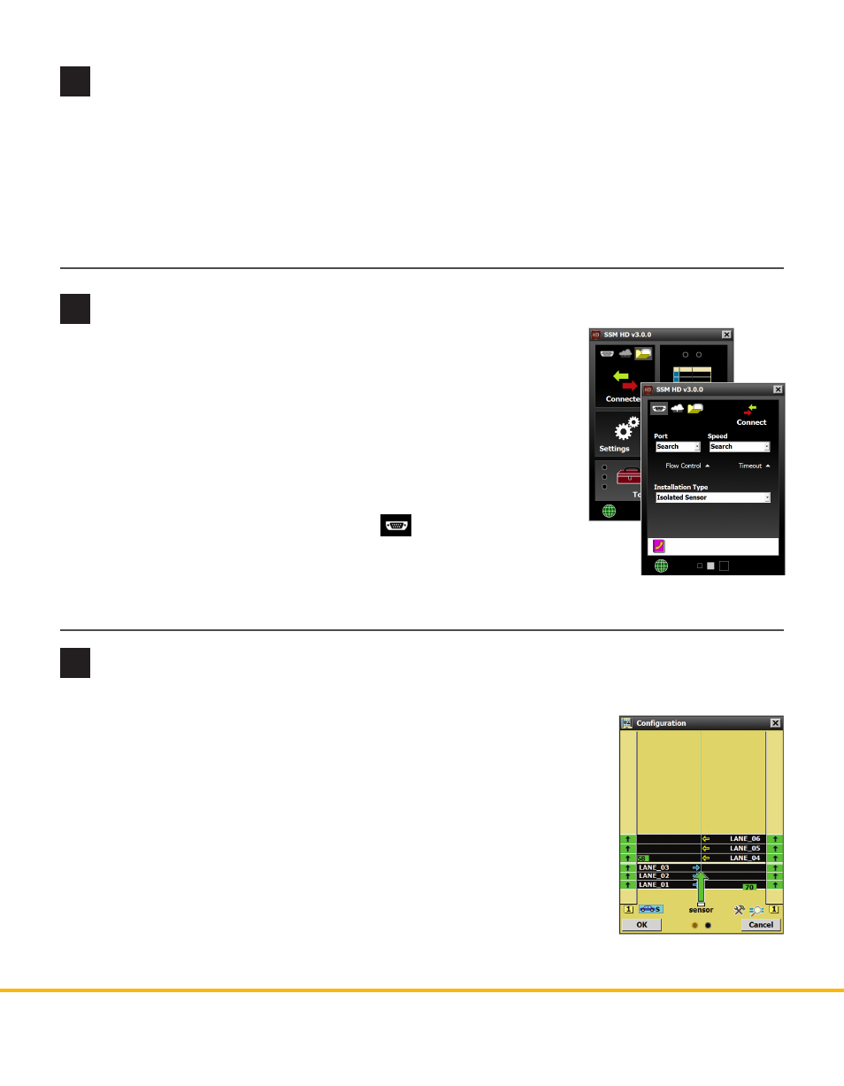
1 Select Lanes from the main menu, then Configuration.
2 Click on the magnifying glass icon and then click Show Alignment. Adjust
the sensor according to the arrow and the colors shown on the detected
vehicles. Green means the sensor is positioned for optimal performance;
yellow or red means the sensor is NOT correctly aligned with the roadway.
3 Once the sensor is properly aligned, tighten the strap screws the rest of the
way.
For the sensor alignment tool to function properly, traffic must be flowing
freely. After each adjustment of the sensor, several vehicles must pass before the
alignment tool’s output is valid. Also, if the sensor is not already aligned close to
perpendicular to traffic, this tool will display a question mark, indicating that the
sensor is too far out of alignment for the tool to function properly.