Wavetronix Click 104 (4-channel DIN rail contact closure) (CLK-104) - Quick-reference Guide User Manual
Click 104 contact closure, Installer quick-reference guide, Mount the device
INSTALLER QUICK-REFERENCE GUIDE
www.wavetronix.com
801.734.7200
Click 104 Contact Closure
2
Mount the device
The Click 104 mounts over a T-bus for power and for the control bus (bus 2):
1 If the Click 104 was shipped with the T-bus connector attached, remove the
connector from the module.
2 Snap the connector onto the DIN rail by positioning it over the rail with the
male connector pointing to the right. Hook one arm over the edge of the
DIN rail and press down on the other arm until it snaps into place.
3 Connect the T-bus connector to the rest of the T-bus by sliding them to-
gether until you hear them snap into place.
4 Mount the Click 104 onto the DIN rail: position it properly over the T-bus
connector, hook the lip over the lower edge of the DIN rail, and use a rock-
ing motion to snap the module into place.
3
Wire power and RS-485 communication
If you are using a Click 200 surge protector with the Click 104, power and communication are provided to
the Click 104 through the T-bus (see the Click 200 Quick-reference Guide). If you don’t have a Click 200
surge protector, use the following steps to wire power and communication into the Click 104:
1 Plug a T-bus 5-screw terminal block into the first T-bus connector.
2 Wire DC power (9–28 V) from the power supply into the first
screw terminal on the 5-screw terminal block; wire -DC into the
second screw terminal.
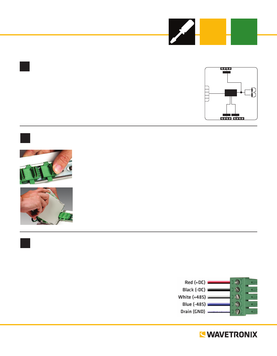
3 Connect RS-485 communication (+485, -485 and GND) to the
remaining three screw terminals on the 5-screw terminal block.
1
Understand buses
RS-232
3-4
1-2
RS-485
Bus 2
Control
Contact
Closures
+DC
-DC
+485
-485
GND
Bus 1
Data
Bus 1
Data
104
Click
The 104 installation process will make more sense if you understand its two buses:
˽
Bus 1: Data – The RJ-11 jacks (for RS-485) and the RS-232 screw terminals
are connected; theyll be used for receiving detection calls
˽
Bus 2: Control – The connector on the back connects to the T-bus (shared
RS-485 bus for multiple Click devices) and is isolated from bus 1; it should be
used to connect to the Click 104 with a computer so you can configure it.