Wire the screw terminals, Connect to the rj-11 jacks – Wavetronix Click 222 (system surge protector) (CLK-222) - Quick-reference Guide User Manual
Page 2
© 2014 Wavetronix LLC. All rights reserved. Protected by US Pat. Nos. 6,556,916; 6,693,557; 7,426,450; 7,427,930; 7,573,400; 7,889,097; 7,889,098; 7,924,170; 7,991,542; 8,248,272;
8,665,113; and Cdn. Pat. Nos. 2,461,411; 2,434,756; 2,512,689; and Euro. Pat. Nos. 1435036; 1438702; 1611458. Other US and international patents pending. Wavetronix, SmartSensor, Click,
Command and all associated logos are trademarks of Wavetronix LLC. All other product or brand names as they appear are trademarks or registered trademarks of their respective hold-
ers. Product specifications are subject to change without notice. This material is provided for informational purposes only; Wavetronix assumes no liability related to its use.
3
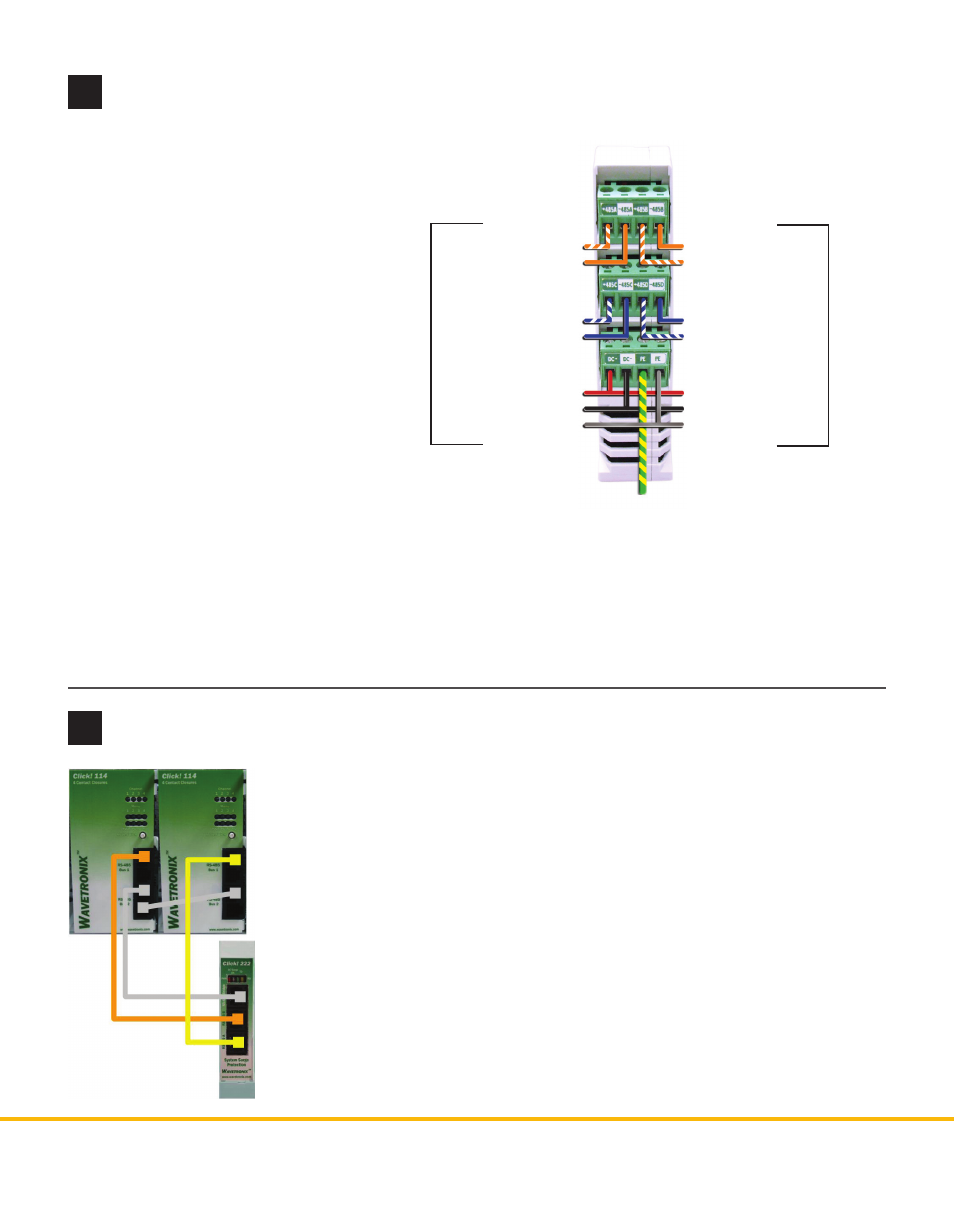
Wire the screw terminals
4
Connect to the RJ-11 jacks
The Click 222 has three RJ-11 jacks, located on the faceplate:
˽
RS-485 A – This jack is tied to the 485A screw terminals. Connect it via a
jumper cable to a contact closure card to receive contact closure informa-
tion from sensor 1.
˽
RS-485 B – This jack is tied to the 485B screw terminals. Connect it via a
jumper cable to a contact closure card to receive contact closure informa-
tion from sensor 2.
˽
RS-485 Bridge – This jack is tied to the 485C and 485D screw terminals, the
T-bus, and the control bridge, which electrically isolates the RS-485 buses
for more reliable communications. This jack is commonly used for the
communications necessary to configure the contact closure cards. If you
want to configure these cards by computer, connect this jack via a jumper
cable to the first rack card to be configured, then daisy-chain all the cards
together.
The Click 222 is designed for use with
a SmartSensor Matrix and SmartSen-
sor 6-conductor cable; the steps to
install this way are listed below. If you
don’t intend to use the Matrix or the
6-conductor cable, skip these steps
and wire RS-485 and power according
to the labels on the terminals.
1 Wire the cable from sensor 1 as
shown at right: the orange wires
to 485A, the blue wires to 485C,
the red wire to DC+, the black to
DC-, and the drain to PE.
2 If you’re using a second sensor,
repeat step 1 with the sensor 2
cable and the 485B and 485D
terminals. As there is only one
each of the DC terminals, they will both have two wires.
Note. Underground cable runs are susceptible to surges, making it necessary to have surge protection on
both ends of the cable. If you are using the SmartSensor Matrix, protection is available through the sensor
itself, so you just need surge protection, like the Click 222, on the non-sensor end of the cable. If you are
using another sensor, though, you will need to use a Click 222 on both ends of the cable: one in the main
traffic cabinet and one in a pole-mount box near the sensor.
WX-500-0180
+485A (Orange/White)
-485A (Orange)
+485C (Blue/White)
-485C (Blue)
+DC (Red)
-DC (Black)
Drain
-485B (Orange)
+485B (Orange/White)
-485D (Blue)
+485D (Blue/White)
+DC (Red)
-DC (Black)
Drain
Earth ground
Sensor 1
Sensor 2