Switch settings ld-64f, Turning time / data rate / connected units – Westermo LD-64F User Manual
Page 7
17
6073-2011
• • •
•
• •
•
•
•
•
•
•
• •
•
•
• •
•
• •
10 10 10 11 11 11
9
Supervision table when selecting data bits
7 bits
8 bits
No parity
Parity
1 stop bit
2 stop bits
Number of bits
Turning Time / Data rate /
Connected units
S1
ON
1 2 3 4 5 6 7 8 9
S1
ON
1 2 3 4 5 6 7 8 9
S1
ON
1 2 3 4 5 6 7 8 9
S1
ON
1 2 3 4 5 6 7 8 9
20
Number**
of units
20
20
20
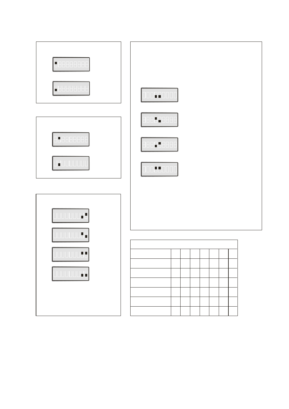
Selection of 2- or 4-wire
4-wire
S1
ON
1 2 3 4 5 6 7 8 9
2-wire
S1
ON
1 2 3 4 5 6 7 8 9
Selection of Master/Slave
Master
S1
ON
1 2 3 4 5 6 7 8 9
Slave
S1
ON
1 2 3 4 5 6 7 8 9
Selection of bits
9
S1
ON
1 2 3 4 5 6 7 8 9
10
S1
ON
1 2 3 4 5 6 7 8 9
11
S1
ON
1 2 3 4 5 6 7 8 9
*
S1
ON
1 2 3 4 5 6 7 8 9
2-wire RS-485 or 4-wire RS-422.
Switch settings LD-64F
0.7 µs
1.5 Mbit/s
Turning-
time
Transmission*
rate
0.8 µs
1.2 Mbit/s
1 µs
1.0 Mbit/s
2 µs
500 kbit/s
* Use this setting for synchronous or other
asynchronous protocols.
The transmitter will be active from the
startbit to 10 bit-times after the last high
databit.
Please note that only one master can be
used per system.
*) For other speeds please contact Westermo
**) Number of units is depending on the data rate and the total
system. "Number of units" means a typical value that can be
changed depending on the structure of the total system.
S1:3, 6 and 7 is not used.