6 settings and connections, S1 ring factory settings, S1 bus transmitted power link 1 – Westermo LR-11 User Manual
Page 15: S1 low power, S1 ring master, S1 slave
15
6608-2211
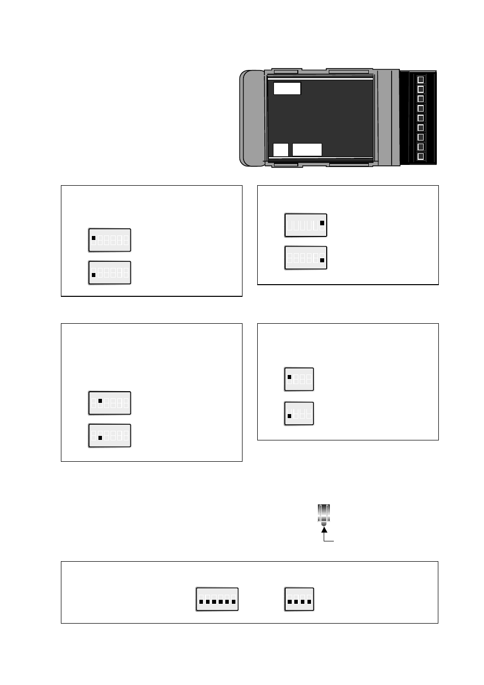
6 SETTINGS AND CONNECTIONS
6.1 Settings
The LR-11 can through different switch
settings be adapted to a variety of oper-
ating conditions. To set the switches,
open the plastic case by removing the
top cover.
The following switch settings will be used:
Bus/Ring configuration
(not PP version)
ON
1 2 3 4 5 6
S1
Ring
Factory settings
ON
1 2 3 4 5 6
S1
ON
1 2 3 4 5 6
S1
Bus
Transmitted power link 1
ON
1 2 3 4 5 6
S1
Low power
ON
1 2 3 4 5 6
S1
High power
Transmitted power link 2
(not PP version)
S3
S3
Low power
S3
High power
Ring master/Slave-mode
(not PP version)
(only possible when ring configuration
is selected with S1:1)
ON
1 2 3 4 5 6
S1
Ring master
ON
1 2 3 4 5 6
S1
Slave
S1: 3, 4 and 5 is not used.
Low power is only recommended with fibre
distances shorter than 100 metres.
S3: 2–4 is not used.
Low power is only recommended with fibre
distances shorter than 100 metres.
ON
1 2 3 4
ON
1 2 3 4
ON
1 2 3 4
Service request button S4
Pressing this button generates service request messages
from each side of the router.
The service button is used for installation in a network
management tool.
Button
1
2
3
4
5
6
7
8
9
S4
S1:1-6
S3:1-4