Wiring the relay output, Wiring the earth ground, Connecting to network – Westermo MCI-211G User Manual
Page 3
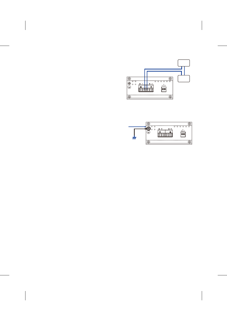
Wiring the Relay Output
The relay output alarm contacts are in the middle of
the terminal block connector as shown in figure-3.
By inserting the wires and settings the DIP switch
of the respective alarm function to “ON”, relay
output alarm will detect port or power fault, and form
a short circuit. The alarm relay output is “Normal Open”. See, Figure -2.
Wiring the Earth Ground
In an industrial environment, there might be devices
that generate electromagnetic noise, such as AC
motors, electric welding machine, or a power
generator. These devices will generate electric
noise or surges that might disturb communications.
To prevent those noises, the device should be well earthed. In the Figure- 3 shows how to make
connection.
Connecting to Network
1. Connecting the Ethernet Ports: Connect one end of an Ethernet cable into the UTP port of
MCI-211G, while the other end is connected to the attached networking device. The UTP ports
support auto MDI/MDIX function. The Speed LED will turn on for 1000M link and blinking for
100Mbps link; the LNK/ACT LED will turn on for link up and blinking for packet transmits and
receives.
2. Install Gigabit SFP transceiver and make the connection:
Connect the fiber port on your MCI-211G to another Gigabit Fiber Ethernet device, by following the
figure below. Wrong connection will cause the fiber port not working properly.
Maximum 1A current / DC 24V
Figure-2
Alarm
System
Extra Power
System
PWR
Port
LFF
Alarm control
DC1
DC2
Alarm
A
B
Earth Ground
Screw
Earth Ground
Warning: Do not connect to AC line-Natural
Figure-3
PWR
Port
LFF
Alarm control
DC1
DC2
Alarm
A
B