Connections md-21, Line connection md-21 terminal connection (dce) – Westermo MD-21 User Manual
Page 4
Receiver
1
R+
Receiver
2
R-
Transmitter
3
T+
Transmitter
4
T-
5
Shield
10
6151-2002
N
115V*/230V
L
AC power
PE/Protective Earth
I
3
8
103
TD/Transmitted Data
O
2
7
104
RD/Received Data
I
7
6
105
RTS/Request To Send
O
8
5
106
CTS/Clear To Send
O
6
2
107
DSR/Data Set Ready
–
5
9 & 1
102
SG/Signal Ground
O
1
4
109
DCD/Data Carrier Detect
NC
4
3
Description
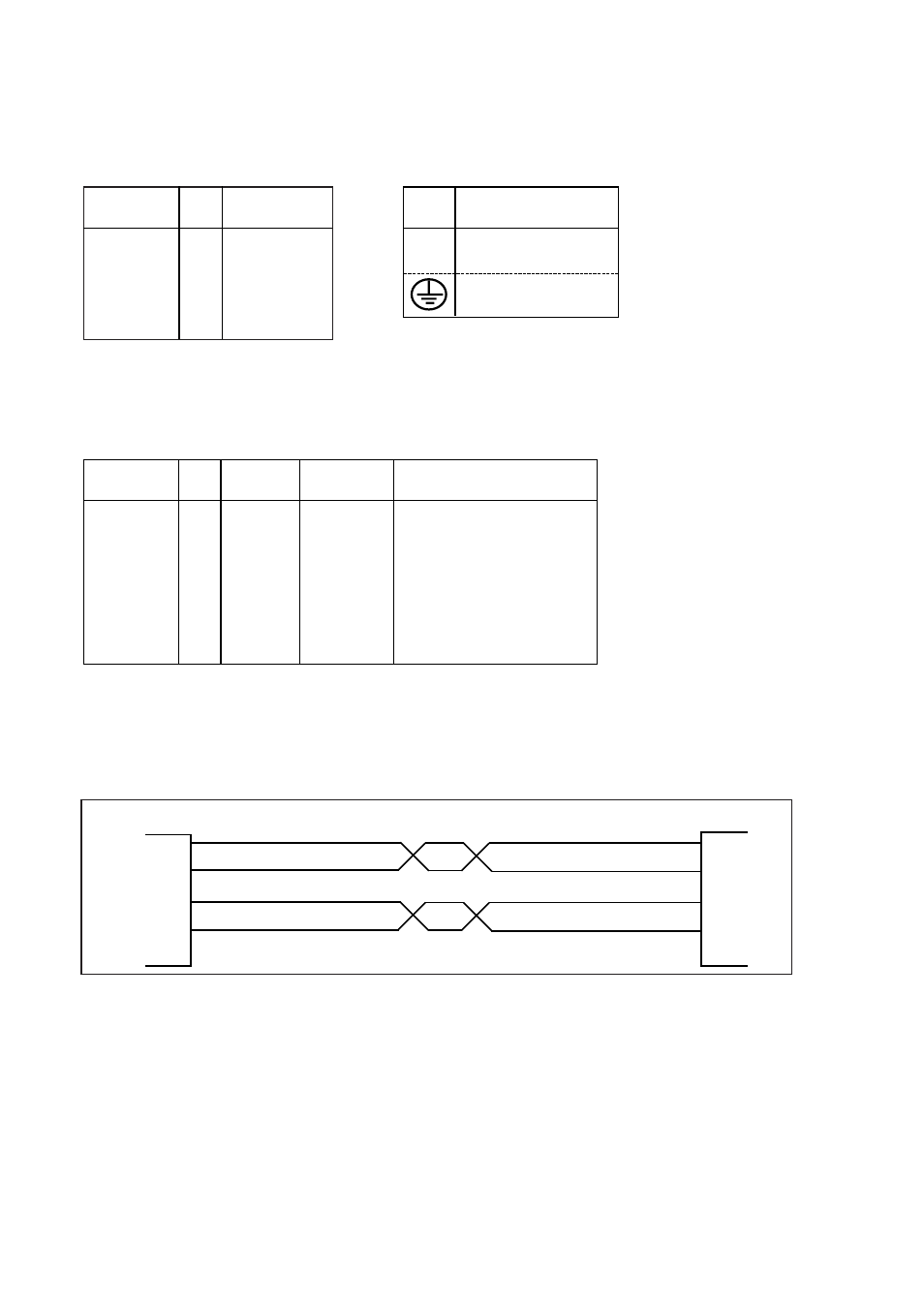
Connections MD-21
Line connection
(5-Position screw-terminal)
MD-21
20mA current loop equipment
Trans-
mitter
Receiver
1
2
3
4
5
R+
R-
T+
T-
T+
T-
R+
R-
Receiver
Trans-
mitter
Shield 1)
Direction
No.
Description
Power connection (AC)
(3-position screw-terminal)
Line connection MD-21
Terminal connection (DCE)
(RS-232-C/V.24, 9-position D-sub female or screw-terminal)
I=input O=output. MD-21 is a DCE (Data Communication Equipment).
NC=not connected.
Screw
no.
Power
Supply
Direction 1)
Pin
no.
Screw
no.
CCITT V.24
Circuit no.
1) If shielded cable is used, connect the shield only at one end to avoid ground currents.
* MD-21 115V