Location of interface ports and led’s – Westermo MCW-211 User Manual
Page 11
Advertising
11
6645-2204
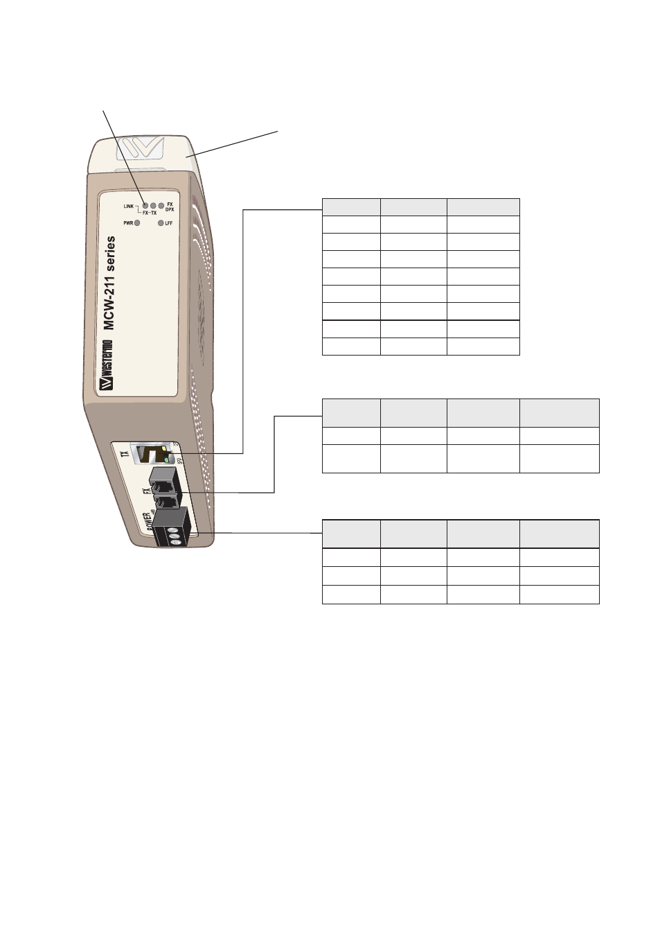
Location of interface ports and LED’s
LED Indicators (for details see page 13)
Ethernet TX – RJ-45
Position
Direction*
Description
1
In/Out
TD+
2
In/Out
TD–
3
In/Out
RD
4
–
–
5
–
–
6
In/Out
RD–
7
–
–
8
–
–
* Direction relative this unit
Ethernet FX – SC, ST or LC
Position
Direction*
Description
Product
marking
Rx
In
Receive port
Rx
Tx
Out
Transmit
port
Tx
* Direction relative this unit
Power
Position
Direction*
Description
Product
marking
1
–
Common
COM
2
In
+ Voltage A
+VA
3
In
+ Voltage B
+VB
* Direction relative this unit
DIP switches are accessible under the lid
Advertising