2 line connection, 3 hints – Westermo MD-45 User Manual
Page 28
28
6157-2003
=Termination
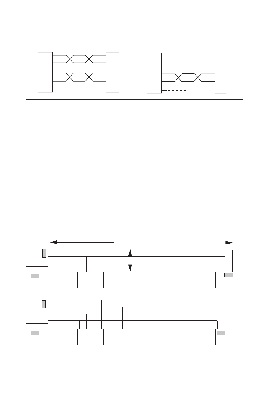
Max 32 connections
Max 1 200 metres
Max 0.3 metre
=Termination
Max 32 connections
A
B
A
B
A
B
A
B
A’
B’
A
B
B’ A’
A’
B
B
A
B’ A’ B A
A
B’
N.B. R+/R–, T+/T– definitions are not standard, it can help to shift A and B
if the unit does not work.
7.2 Line connection
*) If shielded cable is used, connect the shield only at one end to avoid ground currents.
4-wire
MD-45
RS-422/485
equipment
RS-422/485
equipment
Transmitter/
Receiver
Transmitter/
Receiver
Twisted pairs
Twisted pairs
Receiver
Transmitter
Transmitter
Receiver
A’
B’
A
B
A
B
A’
B’
Shield *)
Shield *)
A/A’
A/A’
B/B’
B/B’
1
2
3
4
5
3
4
5
MD-45
2-wire
7.3 Hints
RS-422/485 was designed for multidrop applications. When a system is installed it should
form a bus structure (see diagrams). Star shaped networks should never be created, there
are other Westermo products designed to work in star net applications. To get a correct
installation according to the RS-422/485 specification it´s very important that the line is
terminated at the correct points. The recommendation is to terminate the receiver on
the master unit and the final bus slave unit. See diagrams for details of how this is done
with RS-485 (2-wire) and RS-422 (4-wire).
The line transmitter used in the MD-45 is activated by data received on the RS-232
interface, unlike conventional converters that rely on a control signal (e.g. RTS).
If any problems do occur on set up of the MD-45, the LED’s will be helpful.
• PWR:
The unit has power.
• RD:
Data received on the RS-422/485 interface.
• CTS:
Follows RTS.
• RTS:
Status of RTS from the RS-232 interface.
• TD:
Data received on RS-232 interface.