Westermo ODW-630-F1 User Manual
Page 13
Advertising
13
6651-22641
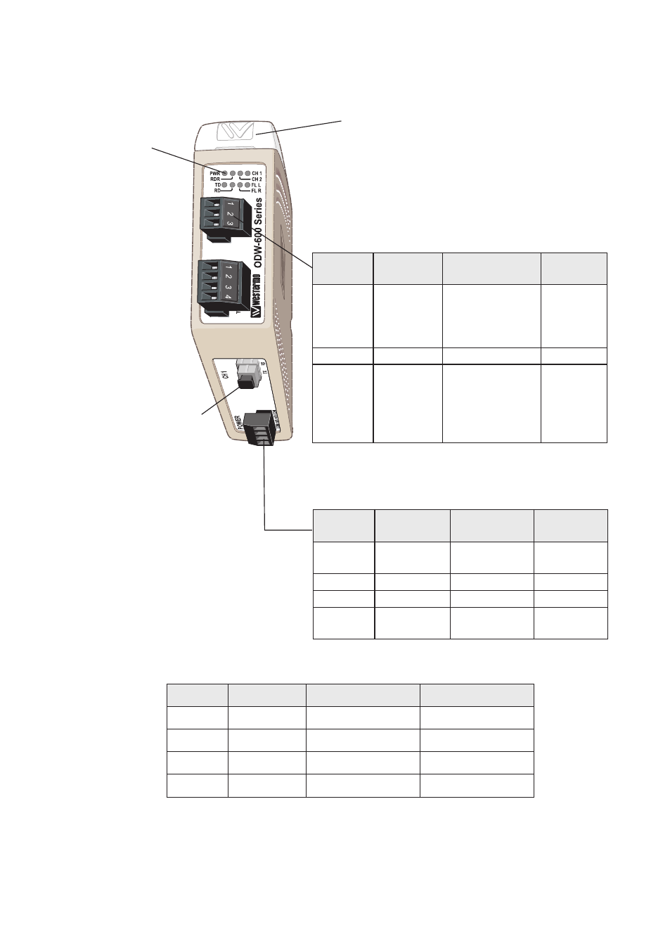
Location of Interface ports, LED’s and DIP-switches
Position Direction* Description
Product
marking
1
In
Common
voltage
COM
2
In
Voltage A
+VA
3
In
Voltage B
+VB
4
In
Common
voltage
COM
Position Direction Description
Product
marking
1
NO
Contact with C
when fibre opti-
cal links are in
operation
NO
2
C
Common
C
3
NC
Open (no con-
tact with C)
when fibre opti-
cal links are in
operation
NC
Position Direction*
Description
Product marking
1
In
R+ (EIA RS-485 A’)
R+
2
In
R– (EIA RS-485 B’)
R–
3
In/Out
T+ (EIA RS-485 A)
T/R+
4
In/Out
T– (EIA RS-485 B)
T/R–
LED Indicators
(for details
see page 14)
DIP-switches accessible under lid
(for details see page 15-17)
FX(Fibre)
(for details
see page 12)
Status
screw terminal
Power
screw terminal
RS-422/485
screw terminal
*
Direction relative this unit
Advertising