Westermo U100 User Manual
Page 6
OnTime Industrial Ethernet
100 Series
V 1.0
- 6 -
Section 1.3
Switches vs. Hubs
A hub consists of a number of ports normally with either RJ-45 (copper) sockets and / or fibre
optic ports that have a number of different styles of fibre optic sockets. Usually a ‘patch cable’
is connected to the hub; the other end is normally connected to a device (PC, Printer etc).
Note: It should be noted that when a hub requires an ‘up-link’ connection to a further
hub a cross-over style cable is required.
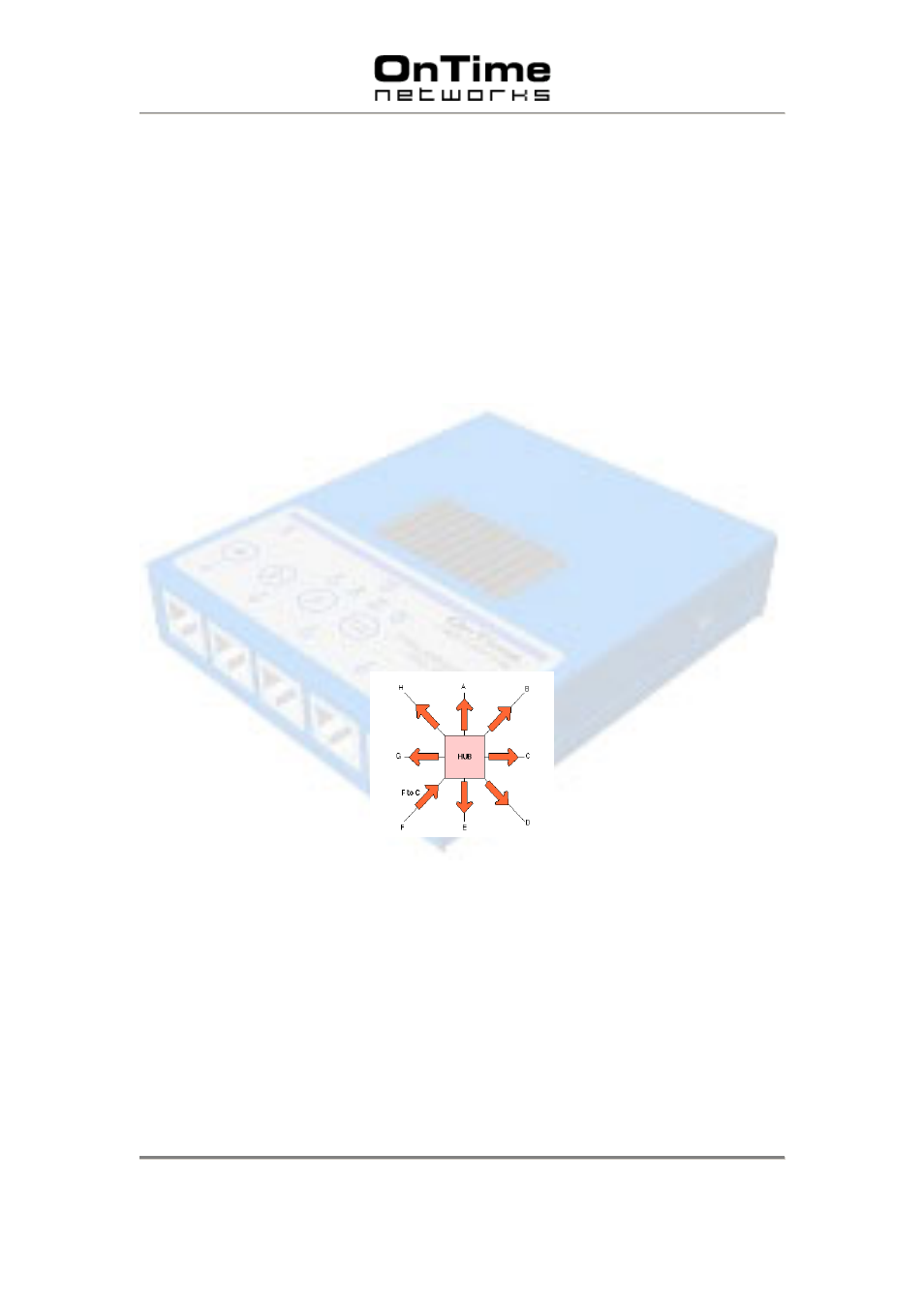
A hub has no intelligence and therefore is unable to identify addresses or any information
contained within
the Header frame of an Ethernet packet. This means that it is not capable of
determining which port to send the frame to. Therefore, every frame is sent to every port
.
Note: Industrial hubs can only connect to equipment that operates at the same speed.
A network of repeaters and hubs is called a ‘Shared Ethernet’ or ‘Collision Domain’. Various
systems will all compete with each other using ‘Carrier Sense Multiple Access / Collision
Detect’ (CSMA/CD) protocol. This means that only one system is allowed to proceed with
a transmission of a frame within a Collision Domain at any one time. This is a major
disadvantage when using Hubs and Repeaters within a network.
If a hub sees a collision on a cable segment, it is detected and a ‘jam’ signal is generated.
The ‘jam’ signal is sent to all connected devices. This ensures that every device is aware of
the collision and they do not attempt to transmit during the collision.
All Ports Receive the Same Ethernet Frame
To summarise, hubs operate with the following limitations:
•
Only a single speed of operation – no ability to automatically change between 10M or
100M.
•
Only one system is allowed to proceed with a transmission of a frame within a
Collision Domain at any one time.
•
Hubs require special ‘crossed’ cables to enables links from Hub to Hub. (If no up-link
port is present)