Airaid 200-129 User Manual
Installation instructions, Component identification
Installation Instructions
For Part Numbers:
200-129
700-469 Airaid Oiled Media Filter
201-129
701-469 SynthaMax Dry Media Filter - Red
202-129
702-469 SynthaMax Dry Media Filter - Black
203-129
703-469 SynthaMax Dry Media Filter - Blue
2001-04 Chevrolet Silverado 2500HD/3500HD
2001-04 GMC Sierra 2500HD/3500HD
6.6L V8 Duramax Diesel “LB7”
(Will NOT fit the 2004 “LLY” Engine)
1. Disconnect the negative battery cable.
A.) Disconnect the Mass Air Flow (M.A.F.)
sensor wiring harness. Using the supplied T-20
Security bit, remove the two screws and the
M.A.F. sensor fr om the tube (save the sensor
for reuse).
B.) Loosen the hose clamps on each end of the
factory intake tube assembly.
3. Remove the factory intake tube assembly from
the engine. Rock the factory air box back and
forth and remove it from the vehicle. There are
only grommets holding it in, no bolts.
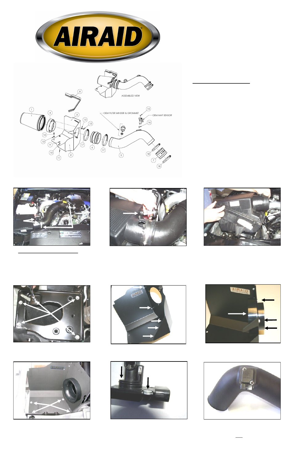
Component Identification
1.
Airaid Premium Filter
1
2. MAF Panel
1
3. Rear Air Dam
1
4. Filter Adapter
1
5. Airaid Intake Tube
1
6. Urethane Hump Hose
1
7. Urethane Coupler
1
8. Weather Strip 19 ½”
1
9.
6-32 x 5/16” Screw
5
10.
#6 Flat Washer
5
11.
6-32 Keps Nut
5
12.
¼ - 20 x 5/8” Hex Bolt
3
13.
¼” Flat Washer
7
14.
M6-1x 25 Hex Bolt
4
15.
8-32 x ½” Button Head 2
16.
Steel Washer
2
17.
#72 Hose Clamp
2
18.
#60 Hose Clamp
2
19.
T20 Security Bit
1
7. Install the Airaid Cool Air Dam assembly in
the engine compartment using four M6-1x25 hex
bolts (#14) and 1/4” flat washers (#13).
4. Using a 10mm socket, remove the five bolts
and mounting plate from the engine compartment.
6. Using three ¼-20 x 5/8” hex bolts (#12) and
1/4” flat washers (#13), install the filter adapter
(#4) onto the Airaid Cool Air Dam.
A.
B.
2. Remove the factory filter minder and grommet
from the side of the factory airbox (save for re-
use).
5. Assemble the Airaid Cool Air Dam panels (#2,
#3) using five 6-32 x 5/16” screws (#9), #6 flat
washers (#10) and 6/32 keps nuts (#11).
9. Using two 8-32 x 1/2” button head screws
(#15) install the factory M.A.F. sensor in the
Airaid intake tube (#5) DO NOT USE THE FAC-
TORY SCREWS! (Note: Sensor must be in-
stalled in the direction shown in the picture, with
steel washers between it and the tube.)
8. Place two steel washers (#16) into the recessed
portions of the MAF sensor mounting holes.
Full color instructions can be viewed on our web site at Airaid.com. Use the Product Search function to find your part number, and click View Details.