Airaid 200-169 User Manual
Installation instructions
Installation Instructions
For Part Numbers:
200-169
700-469 Airaid Oiled Media Filter
201-169
701-469 SynthaMax Dry Media Filter - Red
202-169
702-469 SynthaMax Dry Media Filter - Black
203-169
703-469 SynthaMax Dry Media Filter - Blue
2005-06 Chevrolet Silverado
1500HD/2500HD/3500HD
2007 Chevrolet Silverado “Classic”
1500HD/2500HD/3500HD
6.0L V8
(Does NOT Fit GMC Truck)
Component Identification
1.
Airaid Premium Filter
1
2.
Rear Air Dam Coated
1
3. MAF Panel Coated
1
4. Air Filter Adapter
1
5. Airaid Intake Tube
1
6. Urethane Hump Hose
1
7. GM Coupler
1
8. Weather Strip 21”
1
9 .
6-32 x 5/16” Screw
5
10.
#6 Flat Washer
5
11.
6-32 Keps Nut
5
12.
¼-20 x ½” Button Head Bolt
3
13.
¼” Flat Washer
7
14.
M6-1x25 Hex Bolt
4
15.
#60 Hose Clamp
2
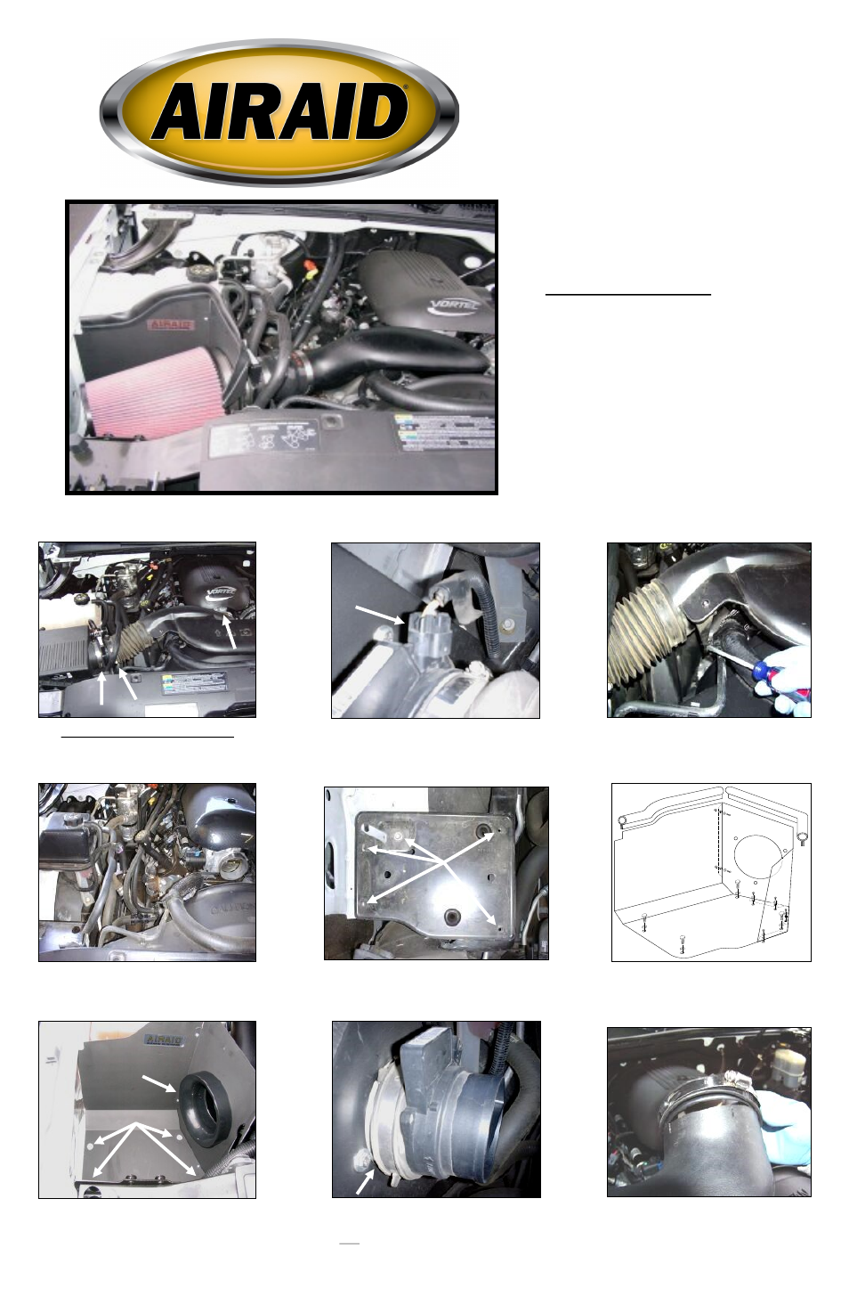
1. Disconnect the negative battery cable.
Loosen the hose clamps located at the Mass Air
Flow (MAF) sensor , and thr ottle body on the
factory intake tube assembly.
2. Disconnect the MAF sensor wiring harness
and remove the sensor from the factory intake
tube.
3. Using a flat head screwdriver, gently pry
the radiator hose bracket from the factory
intake tube assembly and remove the intake
tube from the vehicle.
4. Rock the factory air box back and forth and
remove it from the vehicle. There are only
grommets holding it in, no bolts.
5. Using a 10mm socket, remove the five bolts that
secure the factory air filter housing platform and
remove it.
6. Assemble the Airaid Cool Air Dam pan-
els (#2, #3) using five 6-32x 5/16” screws
(#9), #6 flat washers (#10), and 6-32 keps
nuts (#11).
7. Install the air filter adapter (#4) using three ¼-
20x ½” button head bolts (#12), and 1/4” flat
washers (#13). Position the Airaid Cool Air Dam
in place of the factory airbox & secure it with
four M6-1x25 hex bolts (#14) and 1/4” flat
washers (#13).
8. Slide the factory MAF sensor onto the air
filter adapter and tighten the hose clamp.
(Note: factory clamp / rubber bushing must be
in place on the inlet to the MAF sensor.)
9. Install the GM coupler (#7) onto the throt-
tle body side of the Airaid Intake Tube (#5).
MAF Sensor
Full color instructions can be viewed on our web site at Airaid.com. Use the Product Search function to find your part number, and click View Details.