Airaid 200-207 User Manual
Installation instructions, Component identification
Installation Instructions
For Part Numbers:
200-207
700-422 Airaid Oiled Media Filter
201-207
701-422 SynthaMax Dry Media Filter - Red
202-207
702-422 SynthaMax Dry Media Filter - Black
203-207
703-422 SynthaMax Dry Media Filter - Blue
1999-00 Cadillac Escalade
1996-99 Chevrolet/GMC C/K Pickup 1500
1996-00 Chevrolet/GMC C/K Pickup 2500/3500
1996-99 Chevrolet/GMC C/K Suburban 1500/2500
1999-00 Chevrolet Silverado/GMC Sierra 1500
1996-00 Chevrolet Tahoe/GMC Yukon
1997-00 Isuzu Hombre
4.3L V6, 5.0L V8, 5.7L V8 Vortec Engines
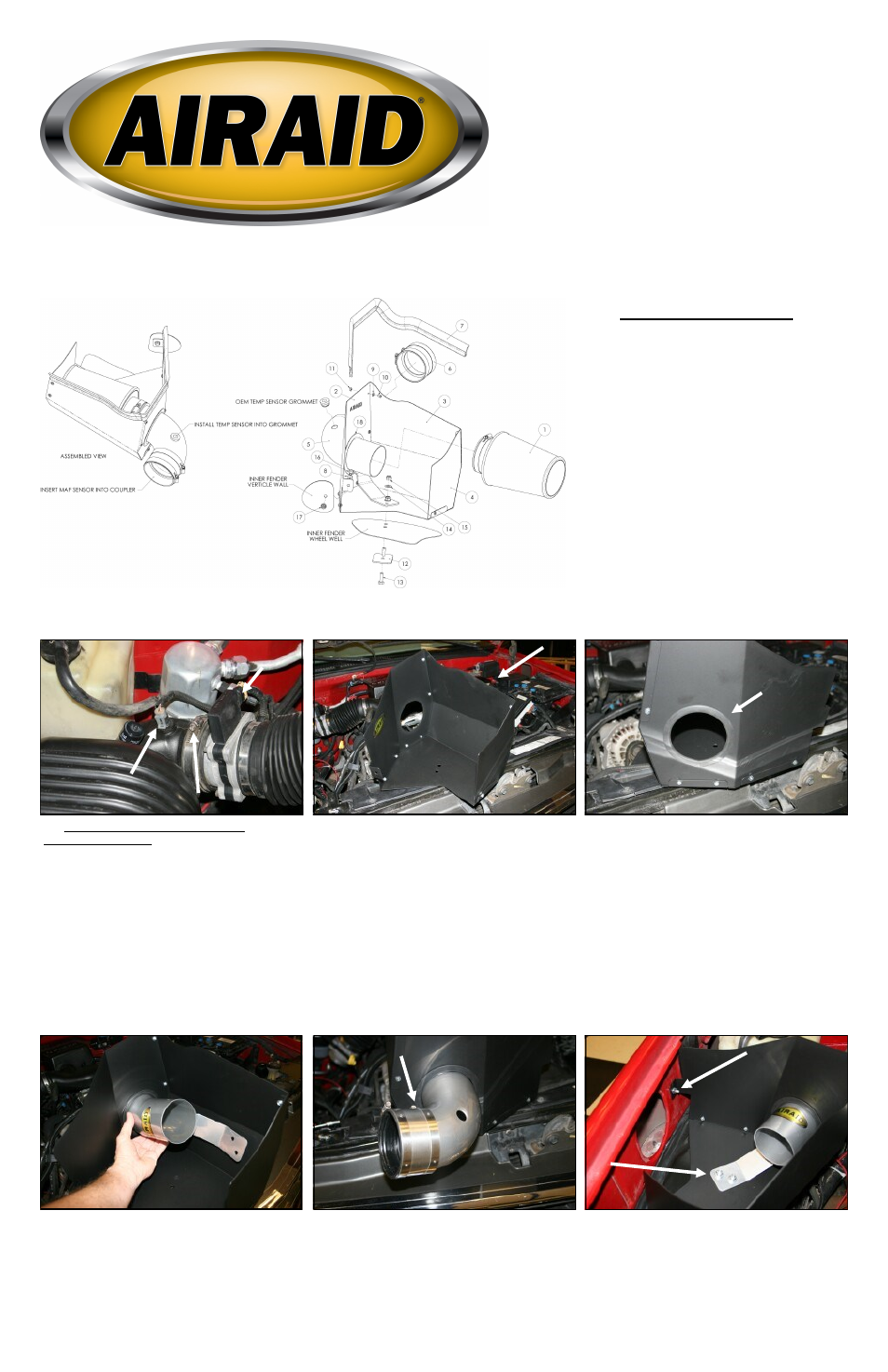
Component Identification
1.
Airaid Premium Filter
1
2. MAF Panel
1
3. Bottom Panel
1
4. End Panel
1
5. Airaid Intake Tube
1
6. Stainless Steel Coupler
1
7. Weather Strip 25 1/4”
1
8.
1/4” Flat Washer
1
9.
#6 Flat Washer
9
10.
6-32 x 5/16” Phillips Screw 9
11.
6-32 Keps Nut
9
12.
3’”x 2” Plate
1
13.
5/16-18 x 1” Hex Bolt
2
14.
5/16” Flat Washer
2
15.
5/16” Nylock Nut
2
16.
1/4-20 x 1/2” Hex Bolt
1
17.
1/4-20 Serrated Nut
1
18.
Rubber Trim 12 1/2”
1
1. Disconnect the negative battery cable.
VERY CAREFULLY! Remove the air intake tempera-
ture sensor first, and then the grommet from the air in-
take tube and set them aside. There is no need to discon-
nect the wiring harness on the temp sensor.
Loosen the hose clamp that secures the air intake tube to
the Mass Air Flow (MAF) sensor.
Disconnect the MAF sensor from the intake tube and
then remove the airbox from the vehicle.
2. Assemble the three Cold Air Dam (CAD) panels (#s
2, 3, &4) as shown using nine 6-32 screws (#10), nine
#6 washers (#9), and nine nuts (#11).
3. Install the supplied rubber trim (#18) into the hole in
the MAF Panel (#2) as shown.
4. Insert the Airaid intake tube (#5) thru the hole in the
MAF panel and then rotate it clockwise so that the holes
in the bracket on the tube line up with the two holes in
the bottom panel.
5. Install the stainless steel coupler (#6) onto the Airaid
intake tube and tighten only the hose clamp on the tube.
6. Install the CAD/Tube assembly into the vehicle as
shown using two 5/16”x 1” bolts (#13) thru the 3” x 2”
plate (#12) up thru the fender well, thru the CAD, and
thru the bracket on the intake tube, secured with two
5/16” flat washers (#14) and two 5/16” nylock nuts
(#15). Next secure the CAD to the side fender well us-
ing one 1/4” hex bolt (#16), 1/4” flat washer (#8), and
1/4” serrated nut (#17). Refer to the line drawing above
if needed.
Mass Air Flow sensor
Rubber Trim
Temperature Sensor
Full color instructions can be viewed on our web site at Airaid.com. Use the Product Search function to find your part number, and click View Details.