Airaid 200-270 User Manual
Installation instructions, Component identification
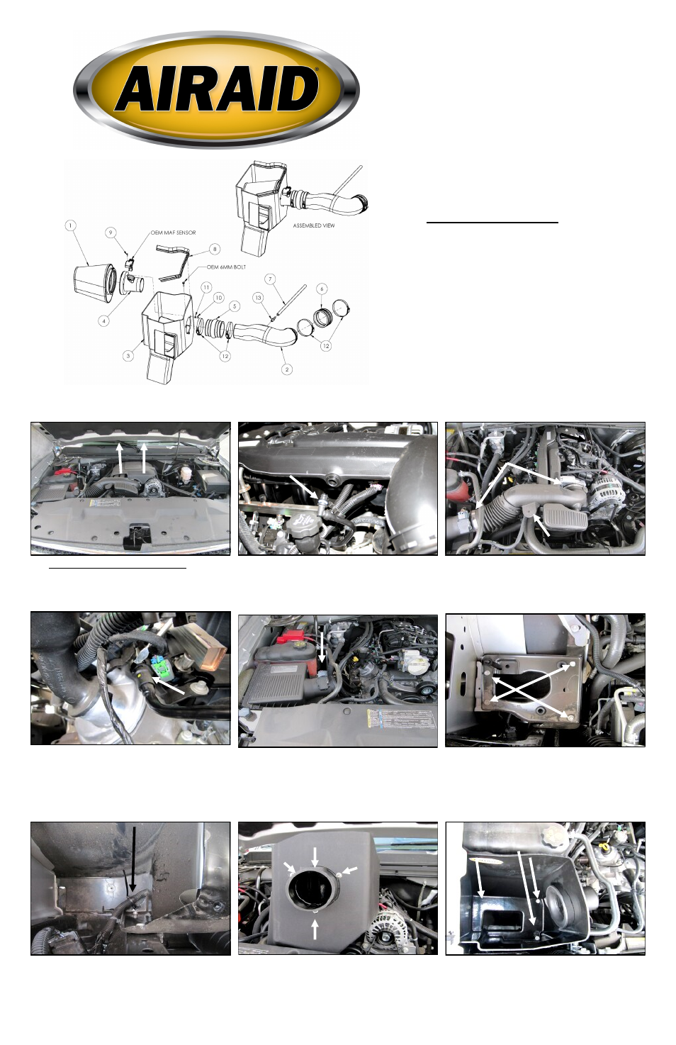
Component Identification
1.
Airaid Premium Filter
1
2. Airaid Intake Tube
1
3. Cold Air Box
1
4. Filter Adapter
1
5. Urethane Hump Hose
1
6. Urethane Coupler
1
7. 3/8”x14” Breather Hose
1
8. Weather Strip 25”
1
9.
8-32 x 1/2” Button Head Screw
2
10.
1/4-20 x 1/2” Button Head Screw 3
11.
¼” Flat Washer
3
12.
#64 Hose Clamp
4
13.
1/4 NPT x 3/8 Barbed Fitting
1
14.
Edge Clip Cable Tie
1
Installation Instructions
For Part Numbers:
200-270
720-472 Airaid Oiled Media Filter
201-270
721-472 SynthaMax Dry Media Filter - Red
202-270
722-472 SynthaMax Dry Media Filter - Black
203-270
723-472 SynthaMax Dry Media Filter - Blue
2009-13 Chevrolet Silverado 1500/Tahoe/Suburban 1500/Avalanche/
GMC Sierra 1500/Yukon/Yukon XL 1500/Denali/Denali XL/
2009-14 Cadillac Escalade/ESV/EXT
4.8L V8, 5.3L V8, 6.0L V8*, 6.2L V8
With Electric Cooling Fans Only
*Does Not Fit 6.0L Engines after 2010
1. Disconnect the negative battery cable.
Remove the engine cover by simply pulling up on it and
sliding out from the vehicle.
2. Pull the PCV breather line from the factory intake
tube.
3.A.) Loosen the clamps securing the factory intake tube
to the throttlebody and the airbox.
B.) Separate the hose anchor from the factory intake and
remove the factory tube.
4. Remove the plastic PCV breather line from the facto-
ry hard line. A standard screwdriver works well for de-
pressing the locking tab in the coupling.
5. Disconnect the Mass Air Flow or MAF sensor and
remove the factory airbox from the vehicle.
The airbox is secured to the vehicle with grommets and
simply lifts out.
6. Remove the four tray bolts and the airbox mounting
tray. Three of the bolts will be reused in step 9.
7. Secure the wiring harness to the inner fender as
shown using the Edge Clip Cable Tie (#14).
8. Install the Filter Adapter (#4) onto the Cold Air Box
or CAB (#3) as shown using the three 1/4-20 Button
Head Screws (#10) and 1/4” Flat Washers (#11).
Note: The MAF socket is to be in the 12:00 position
when properly assembled.
9. Install the CAB ( #3) into the engine compartment
and secure using three of the tray bolts from step 6.
A
B
A
B
C
MAF Socket
B
Full color instructions can be viewed on our web site at Airaid.com. Use the Product Search function to find your part number, and click View Details.