Airaid 250-252 User Manual
Installation instructions, Component identification, For part numbers
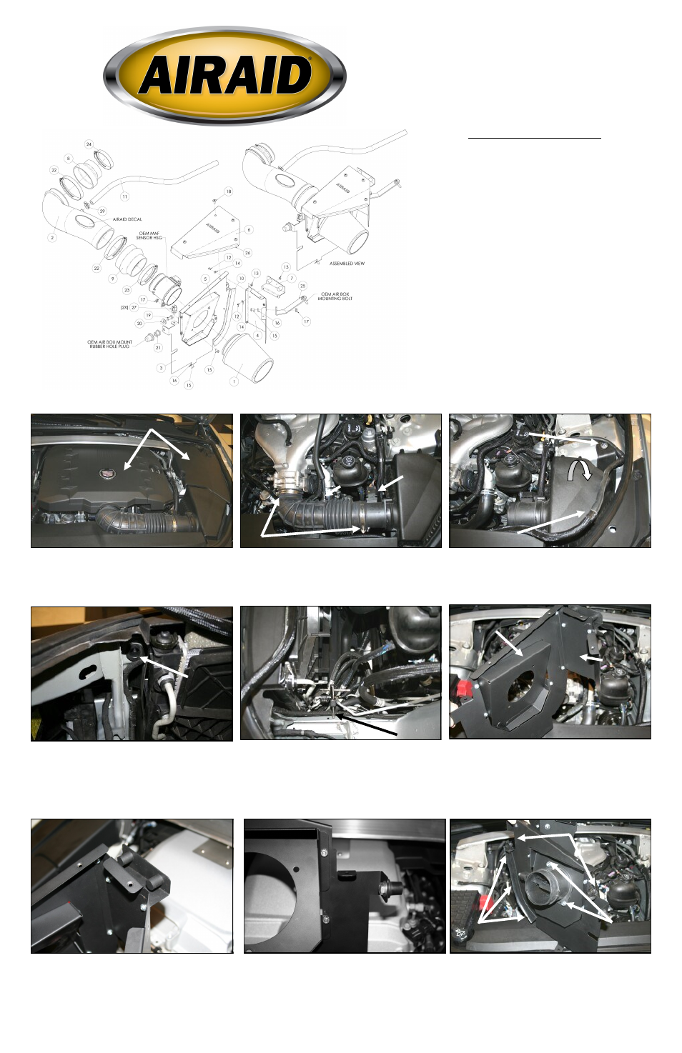
Component Identification
1.
Airaid Premium Filter
1
2.
Airaid Intake Tube
1
3.
MAF Panel
1
4.
Rear Panel
1
5.
Adapter Panel
1
6.
Top Cover
1
7.
OEM Cover Bracket
1
8.
Silicone Reducer Coupler
1
9.
Silicone Hump Hose
1
10.
Weather Strip 9 3/4”
1
11.
1/2”x 26”Breather Hose
1
12.
6-32 x 5/16” Phillips Head Screw
8
13.
6-32 Kep Nut
8
14.
#6 Flat Washer
8
15.
1/4-20 x 1/2” Button Head Screw
4
16.
¼” Flat Washer
2
17.
1/4-20 Serrated Nut
3
18.
1/4-20x1/2” Phillips Head Screw
4
19.
5/16-18 x 3/4” Hex Bolt
1
20.
5/16” Flat Washer
1
21.
5/8” Well Nut
1
22.
#64 Hose Clamp
2
23.
#52 Hose Clamp
1
24.
#48 Hose Clamp
1
25.
Bracket
1
26.
Rubber Edge Trim 8”
1
27.
5/8” Hose Fir Tree Anchor
2
28.
Edge Clip Cable Tie
2
29.
Black Speed Clamp
1
1. Disconnect the negative battery cable.
Remove the engine and shock tower covers, if so
equipped, by simply pulling up on them, and sliding out
from the vehicle. These will be reused later in step 16
2. A) Loosen the hose clamps on the factory intake tube.
B) Disconnect the breather line and remove the factory
intake tube . C) Disconnect the Mass Air Flow sensor.
3. A) Remove the factory fender bolt securing the air
box assembly. Next pull out the coolant line from atop
the air box lid and gently rotate the air box assembly
towards the front of the vehicle. The air box assembly is
now free and should be removed from vehicle.
4. Use caution not to loose the factory core support
grommet while removing the air box assembly. It will be
needed in step 13.
.
5. Locate the pre existing hole in the chassis and tap it
for a 1/4-20 bolt. Use a 1/4-20 NC tap with anti-seize
lube or equivalent, and follow the 1/4 turn forward, 1/2
turn back rule. This will ensure that clean threads will be
cut into the hardened steel. NOTE: If your vehicle has
a grounding cable bolted to the chassis in this location,
you are omit this step.
6. Install the Adapter Panel (#5) to the MAF Panel (#3)
as shown using four 6-32 screws (#12), 6-32 Kep nuts,
and #6 flat washers (#14). Attach the Rear Panel (#4) to
the MAF Panel using two 6-32 screws.
7. Attach the OEM Cover Bracket (#7) to the Rear Panel
a shown using the remaining two sets of 6-32 hardware
8. Attach the 5/8” Well Nut (#22) to the vertical MAF
Panel tab as shown using the 5/16 Hex Bolt (#20) and
the 5/16” flat washer ( #21).
Refer to the Exploded View Drawing for additional
information on part locations and orientations.
9. A) Transfer the Mass Air Flow Sensor from the facto-
ry airbox to the Adapter Panel and secure using two 1/4-
20 button Head Screws (#15) and Serrated Nuts (#17).
Note: The factory airbox seal on the Mass Air Flow Me-
ter is not to be used in this kit. B) Attach the Weather
Strip (# 11) to the curved edge of the MAF Panel. C)
Insert the 5/8” hose anchors (#28) into the two horizon-
tal tab holes on the MAF panel.
A
B
A
B
A
Installation Instructions
For Part Numbers:
250-252
700-452 Airaid Oiled Media Filter
251-252
701-452 SynthaMax Dry Media Filter - Red
252-252
702-452 SynthaMax Dry Media Filter - Black
253-252
703-452 SynthaMax Dry Media Filter - Blue
2008-11 Cadillac CTS 3.6L V6 All models
C
# 4
# 3
# 5
Coolant Line
C
Full color instructions can be viewed on our web site at Airaid.com. Use the Product Search function to find your part number, and click View Details.