Airaid 250-261 User Manual
Installation instructions, Component identification
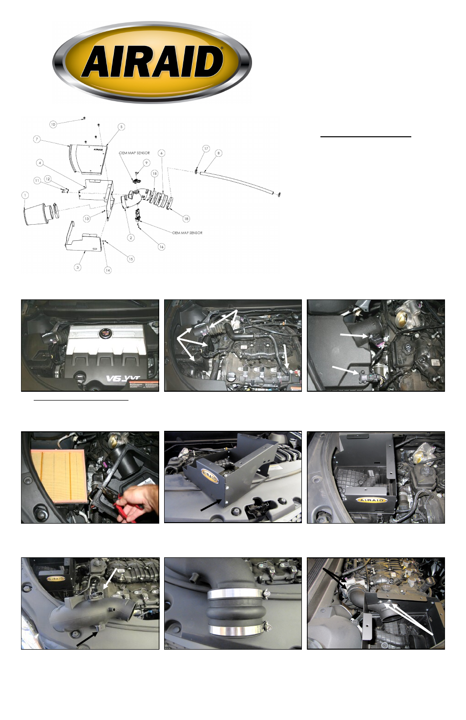
Component Identification
1.
Airaid Premium Filter
1
2.
Airaid Intake Tube
1
3.
Front Panel
1
4.
Rear Panel
1
5.
Top Panel
1
6.
Urethane Hump Hose
1
7.
Rubber Edge Trim 10 3/4”
1
8.
1/2” Breather Hose 23”
1
9.
1/4-20 x 3/4” Hex Bolt
1
10.
¼-20 x ½” Phillips Head Screw
4
11.
1/4-20x 1/2” Button Head Bolt
2
12.
1/4” Flat Washer
2
13.
#6-32 Kep Nut
4
14.
#6 Flat Washer
4
15.
#6-32 x 5/16 Pan head screw
4
16.
#8-32 x 1/2” Button Head Screw 2
17.
#16 Speed Clamp
2
18.
#52 Hose Clamp
2
1. Disconnect the negative battery cable.
Remove the oil fill cap and then lift up on the front of
the engine cover to remove it from the vehicle. Replace
the oil cap for now to make sure nothing falls into the
valve cover during the install.
2. A) Loosen the hose clamps on the factory intake tube.
B) Disconnect the crank case breather line at the valve
cover, and remove the factory intake tube. C) Unfasten
the 3 Factory air box clips.
3. Disconnect the Mass Air Flow, or MAF sensor (A)
and the MAP sensor (B) from the factory airbox lid.
4.Turn the factory airbox lid over and locate the wire
harness anchor. Using a pair of needle nose pillars, com-
press the ribs of the anchor and remove it. Remove the
factory air filter and set it aside.
5. Join the two Airaid panels together with the folded
tabs on the outside, using the four 6-32 screws (#15 ),
#6 Flat washers (#14), and #6 Keps Nuts (#13).
6. Slip the Airaid Panel tabs into the slots in the factory
airbox and
partially install the Panel assembly onto low-
er half of the factory airbox as shown. Do not latch the
airbox clips at this time.
7. Transfer the air sensors from the factory airbox lid
into the Airaid Intake Tube(#2) as shown. Do Not Use
The Factory Hardware. Secure the Mass Air Flow
sensor using the two #8-32 screws (#16), and the MAP
sensor using the 1/4-20x 3/4 hex head bolt (#9) and 1/4”
Flat Washer (#12).
8. Place a #52 Hose Clamp (#18) onto each end of the
Hump Hose (#6), and slide onto the Throttle body side
of the Intake Tube as shown. Do not tighten the clamps
at this time.
9. A) Insert the Filter end of the Intake Tube into the
Panel assembly opening and guide the Coupler side onto
the throttle body. B) Rotate the Intake Tube until the
mounting holes are aligned with the Panel holes. Secure
the Intake Tube to the panel assembly using the two 8-
32 button head screws (#16). C) Tighten the Hose
Clamps, and fasten the airbox clips at this time.
A
B
A
C
B
Installation Instructions
For Part Numbers:
250-261 700-450 Airaid Oiled Media Filter
251-261 701-450 SynthaMax Dry Media Filter - Red
252-261 702-450 SynthaMax Dry Media Filter - Black
253-261 703-450 SynthaMax Dry Media Filter - Blue
2010 –11 Cadillac SRX 3.0L V6
C
B
Folded tab on
outside
MAP sensor
Mass Air Flow sensor
Full color instructions can be viewed on our web site at Airaid.com. Use the Product Search function to find your part number, and click View Details.