Airaid 300-107 User Manual
Installation instructions
Installation Instructions
For Part Numbers :
300-107
700-450 Airaid Oiled Media Filter
301-107
701-450 SynthaMax Dry Media Filter - Red
302-107
702-450 SynthaMax Dry Media Filter - Black
303-107
703-450 SynthaMax Dry Media Filter - Blue
1997-03 Dodge Dakota 2.5L I4, 3.9L V6, 5.2L
& 5.9L V8
1998-03 Dodge Durango 5.9L V8
Component Identification
1.
Airaid Premium Filter
1
2.
Tube Assembly
1
3.
6mm nut
1
4.
½” Fender Washer 1
5.
¼” Self Tapping Screw 1
Full color instructions can be viewed on our web site at Airaid.com. Use the Product Search function to find your part number, and click View Details.
I DISCONNECT NEGATIVE (-) BATTERY CABLE.
II Remove air cleaner assembly.
a) Disconnect air tube from air box.
b) Remove air box lid and filter.
c) Remove air cleaner assembly from fender. Loosen nut at rear near washer reservoir. Remove plastic stud from filter box snout, then re-
move assembly from vehicle.
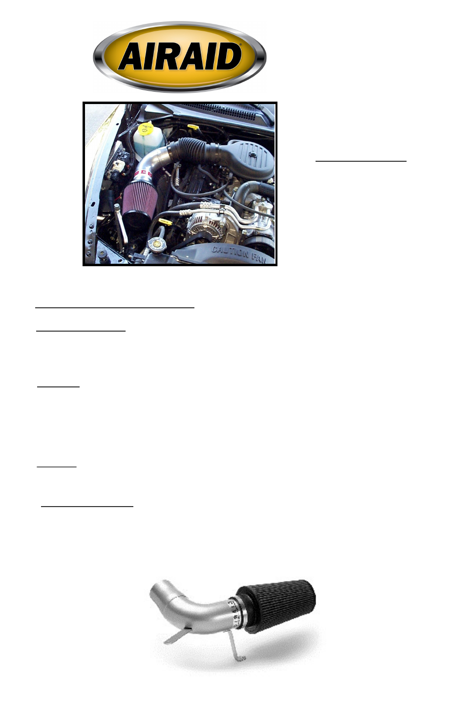
III Install Airaid.
a) Utilizing the original air cleaner stud mount points to install the AIRAID assembly
b) Place supplied 1/2” fender washer on lower stud.
c) Lower AIRAID assembly onto the two studs. Slip intake tubing over AIRAID outlet. Do not tighten yet.
d) Place supplied 6mm nut on the lower stud.
e) Use the original 6mm nut to secure the upper stud mount bracket.
f) Place the cone air filter on intake side of AIRAID assembly and tighten
h) Align and position “AIRAID” on the engine. When satisfied, fully tighten all connections.
IV Finishing up.
a) Check over all work. Make sure no foreign objects are in the intake path!
b) Reconnect battery cable. Enjoy!
V * Addendum for 2000-2003 5.9L
a) Cruise Control must be relocated forward 3”. With out removing from vehicle, unbolt from fender then disconnect cruise cable and vac
uum line from throttle linkage and vacuum source. Reroute cable and vacuum line in front of A/C compressor line and reconnect. Position
C.C. 3” forward. The rear mount hole now will use the front mount. For the bottom mount use the supplied self-tapping screw in an exist
ing hole 3” forward of the original mount.