Airaid 310-136 User Manual
Fig#1 fig#2, Installation instructions
Installation Instructions
For Part Numbers:
310-136
700-450 Airaid Oiled Media Filter
311-136
701-450 SynthaMax Dry Media Filter - Red
312-136
702-450 SynthaMax Dry Media Filter - Black
313-136
703-450 SynthaMax Dry Media Filter - Blue
1991-01 Jeep Cherokee
4.0L I6
Component Identification
1.
Airaid Premium Filter
1
2.
Right Panel Black
1
3.
MAF Panel Black
1
4.
136 Plastic Adapter Tube
1
5.
Weather Strip 32 ½”
1
6.
6-32 x 5/16” Screw
4
7.
6-32 Nut
4
8.
#6 Flat Washer
4
9.
¼-20 Bolt
2
10.
¼” Lock Washer
2
11.
Rubber Cap
1
12.
½” x 7” Hose
1
13.
#16 Speed Clamp
2
Full color instructions can be viewed on our web site at Airaid.com. Use the Product Search function to find your part number, and click View Details.
I
DISCONNECT NEGATIVE (-) BATTERY CABLE
II
Remove Factory Air Box Lid
A) Loosen the factory intake tube clamp at the air box lid using a flat head screwdriver. Refer to Fig #1
C) Disconnect the br eather hose from the passenger side of the factory air box lid. Refer to Fig #1
D) Unclip the factory air box lid and remove fr om engine compartment. See Fig #1
III
Assemble the Airaid Intake System
A) Mount the black plastic adapter tube onto the Airaid Cool Air Dam and fasten using the two 1/4-20 button head bolts and two lock
washers provided. See Fig #2
B) Assemble the two Airaid Cool Air Dam panels using the small screws, nuts, and washers provided. See Fig #2
IV
Install the Airaid Intake System
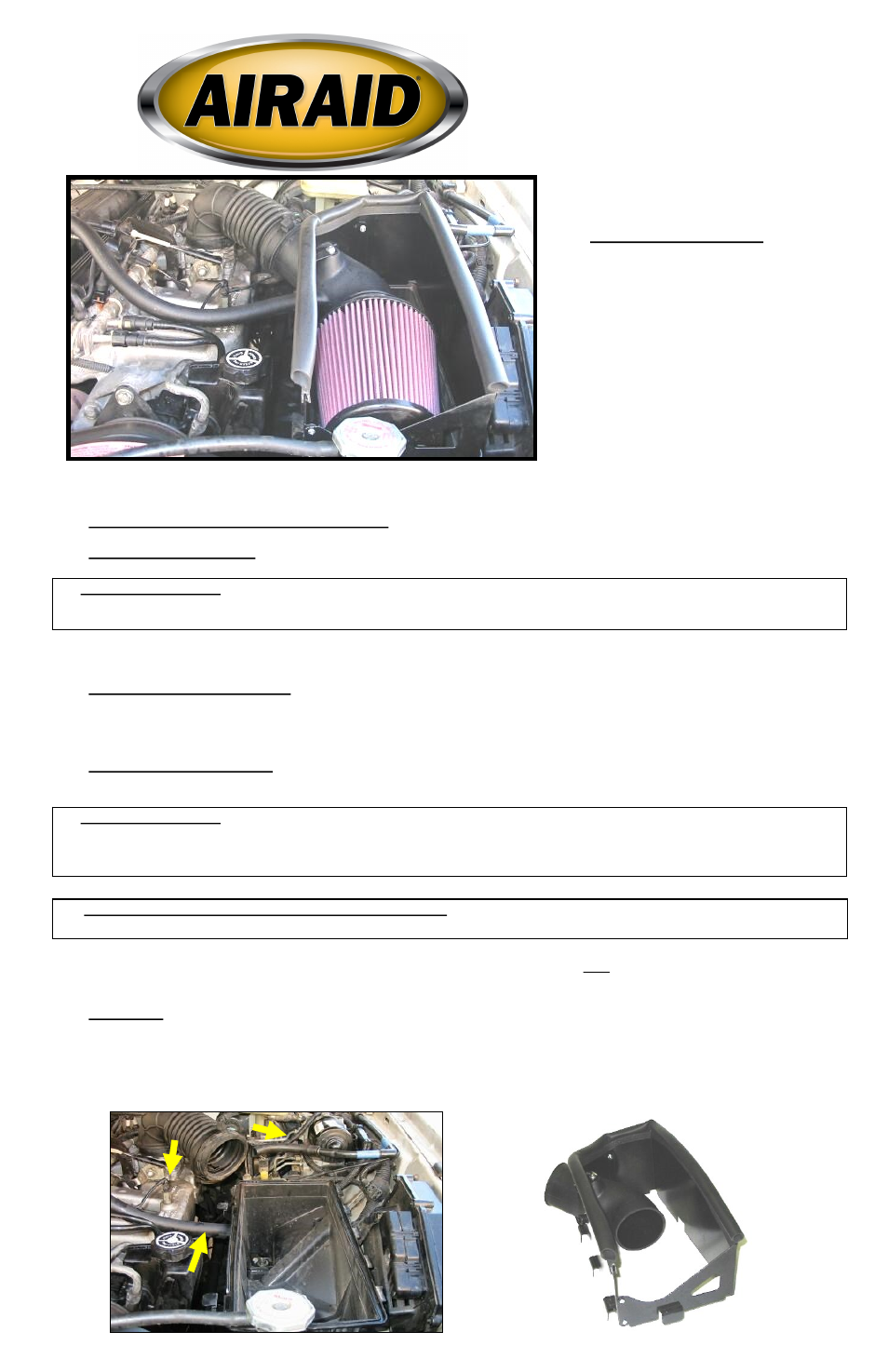
A) Position the Airaid Cool Air Dam in place of the original factory air box lid and snap into place. See Fig #3
B) Connect the factory tube onto the Airaid plastic tube using the factory hose clamp. Refer to Fig #3
D) Reattach the breather hose to the Airaid plastic adapter tube. Refer to Fig #3
F) Mount the Airaid Pr emium Filter to the plastic adapter inside the air dam. Refer to Fig #3
G) Press the provided weather seal onto the top rim of the Airaid system. Refer to Fig #3 (Hint: Start at a corner of the air dam for ease
of installation.)
V
Finishing Up
A) Inspect overall work and check hood clearance.
B) Ensure that no foreign objects are in the intake path!
C) Re-connect negative battery cable.
1991-1995 Models Only:
B) Disconnect the vacuum hose located on the driver side rear of the factory air box. Next disconnect the small vacuum line wher e it at-
taches to the intake manifold. Be careful with the plastic line as it is fragile. It is only moved to enable the install. Refer to Fig #1
1991-1995 Models Only:
C) Reattach the small vacuum line to the factor y locations, including the manifold. Replace the short factory hose located on t he plastic
factory tube, with the longer ½”x 7” extension hose and secure on the intake tube nipple using the two #16 black Speed clamps included.
Refer to Fig #3 
1996-2001 Models Only: You do not have the ½” breather line.
E) Plug the nipple on the driver’s side of the Airaid tube with the black rubber cap provided. Refer to Fig #4
Fig#1
Fig#2
Vacuum Line
Breather Hose