Airaid 310-132 User Manual
Installation instructions, A. b. component identification, C. d
2. A.) Disconnect the air temp sensor in the factory
intake. B.) Remove the two 6 mm bolts holding the
intake tube to the fan Shroud. C.) Loosen the Clamps
on both sides of the factory intake tube. D.) Unclip the
coolant line from the intake tube and remove it from the
vehicle.
3. Disconnect the crankcase breather line in the top of the
airbox. Remove the entire airbox as an assembly by un-
seating it from the mounting grommets in the inner fender
and lifting upward.
4. Install The Filter Adapter (#5) in the Cold Air Box
(#3) using three 1/4-20 x 1/2” Button Head Bolts (#18)
and 1/4” Flat Washers (#11).
5. Install the Air Scoop Bracket (#9) into the Cold Air
Box as shown by using four 1/4-20 x 5/8 Hex Bolts
(#17), 1/4” Flat Washers (#11), and 1/4” Nylock Nuts
(#16).
6. Drill out the rivet heads on the factory airbox and re-
move the air scoop.
8. Firmly place the air scoop into a bench vice and cut
along the line created in step 7 using a hack saw or
equivalent.
7. Set the factory air scoop on a workbench and mark all
four corners at the three inch mark using a scratch awl.
Using a straight edge and the awl, scribe a line connect-
ing all four corners.
9. Insert the factory air scoop into the Cold Air Box and
secure it using two 8-32 x 3/8” Button Head Bolts (#13),
#8 Flat Washers (#14), and #8 Kep Nuts (#15).
A.
B.
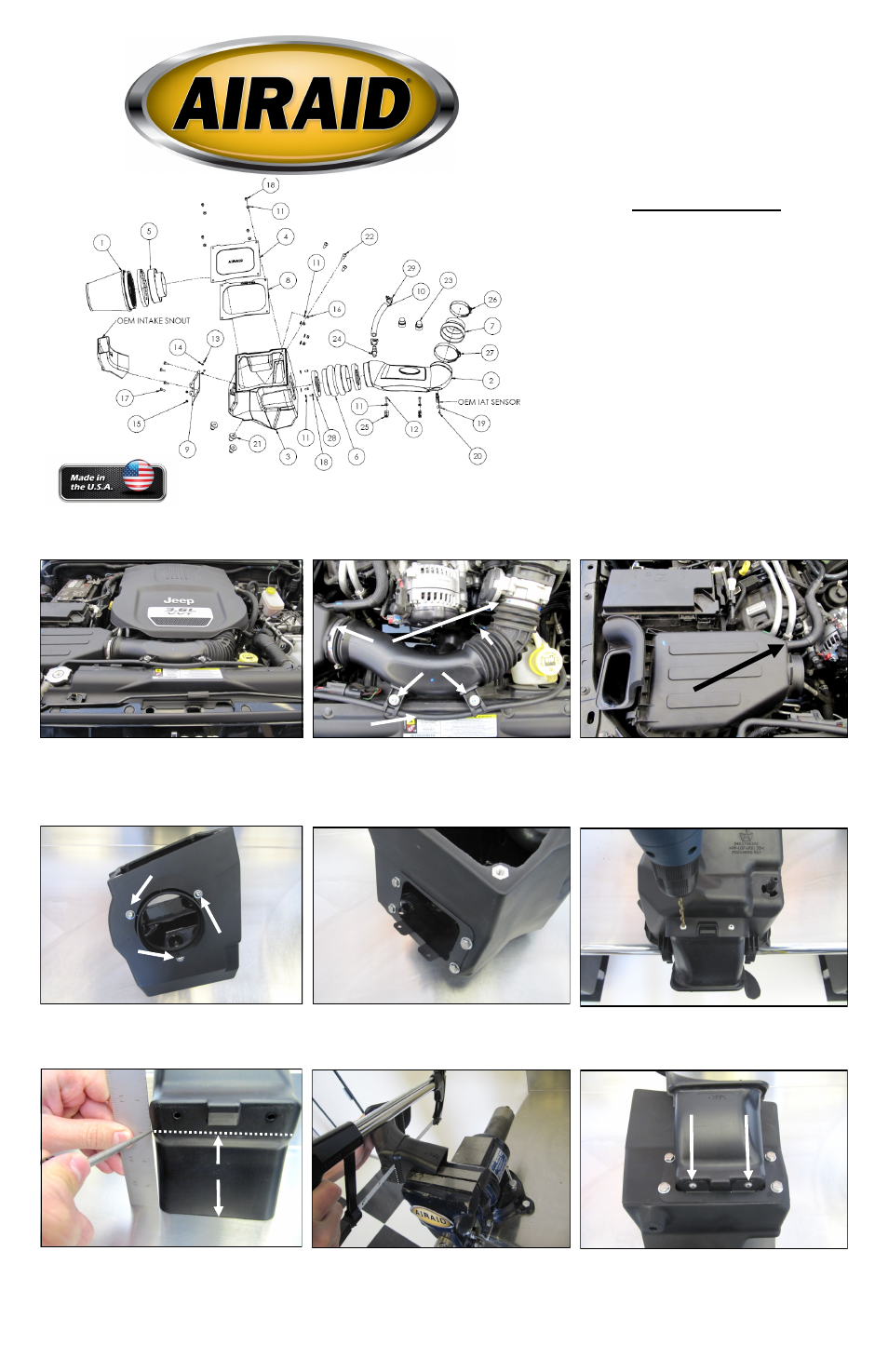
Component Identification
1.
Airaid Premium Filter
1
2.
Intake Tube
1
3.
Cold Air Box
1
4.
Airbox Lid
1
5.
Filter Adapter
1
6.
Double Hump Hose
1
7.
Silicone Reducer
1
8.
Airbox Lid Gasket
1
9.
Air Scoop Bracket
1
10.
5/8” Hose 7 1/2” long
1
11.
1/4” Flat Washer
13
12.
6mm x 1.0-20 Bolt
2
13.
8-32 x 3/8”Button Head Bolt
2
14.
#8 Washer
2
15.
#8 Kep nut
2
16.
1/4” Nylock Nut
4
17.
1/4-20 x 5/8” Hex Bolt
4
18.
1/4-20 x 1/2” Button Head Bolt
7
19.
#8 Fender Washer
1
20.
#8-32 x 1/2 Button Head Bolt
1
21.
3/8-16 Well Nut
3
22.
3/8-16 x 1 1/2” Button Head Bolt
3
23.
Engine Cover Grommet
2
24.
3/8 NPT x 5/8 Barbed Fitting
1
25.
1/2” Adel Clamp
2
26.
#48 Hose Clamp
1
27.
#64 Hose Clamp
1
28.
#72 Hose Clamp
2
29.
#19 Speed Clamp
2
Disconnect The Negative Battery Terminal!
1. Remove the engine cover and set it aside.
C.
D.
3”
Advisory Note: Installation of this intake system requires minor modi-
fications be made to the factory air box. Please read through these in-
structions in their entirety before beginning the procedure.
Installation Instructions
For Part Numbers:
310-132
700-462 Airaid Oiled Media Filter
311-132
701-462 SynthaMax Dry Media Filter - Red
312-132
702-462 SynthaMax Dry Media Filter - Black
313-132
703-462 SynthaMax Dry Media Filter - Blue
2012-15 Jeep Wrangler
3.6L V6
Full color instructions can be viewed on our web site at Airaid.com. Use the Product Search function to find your part number, and click View Details.