Airaid 310-176 User Manual
Installation instructions, Component identification, For part numbers
Installation Instructions
For Part Numbers:
310-176
700-452 Airaid Oiled Media Filter
311-176
701-452 SynthaMax Dry Media Filter - Red
312-176
702-452 SynthaMax Dry Media Filter - Black
313-176
703-452 SynthaMax Dry Media Filter - Blue
1991-1995 Jeep Wrangler
2.5L I4
(DOES NOT FIT WITH OPTIONAL ANTI-
LOCK BRAKE SYSTEM)
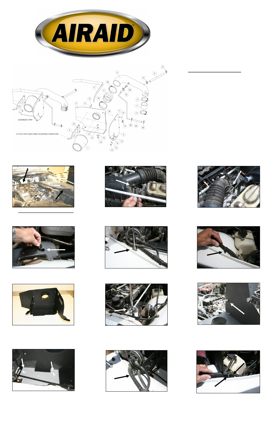
1. Disconnect the negative battery cable.
Remove the factory valve cover breather hose
from the airbox , and the valve cover.
2. Disconnect the vacuum line from the airbox
and at the canister below the master cylinder.
(Save for reuse.)
3. Pry open the plastic clamp that holds the fac-
tory intake tube to the throttle body. Unhook the
3 metal latches on the airbox that hold it to the
mounting plate, and remove the intake assembly.
4. Remove the two grommets from the airbox
mounting plate.
5. Using a 10mm socket, remove the horn bolt
from the fender. (Save for later use.)
6. Carefully remove the wire loom clamp from
the hole in the inner fender. Use caution not to
damage the clamp, as it will be reused.
7. Assemble the Cool Air Dam (CAD) panels
(#2, #3, & #4) as shown using the 5 provided
screws (#10), washers (#11), and nuts (#12).
8. Using a 9/16” wrench, loosen the nut on the
radiator support rod, and lift it up out of the slot.
9. Carefully slide the CAD over the support
rod, and then slide the supplied grommet over
the rod, and into the hole in the CAD as shown.
Rotate the CAD and place it into position on the
factory airbox mount. Re-install the radiator
support rod, and tighten the nut.
Component Identification
1.
Airaid Premium Filter
1
2.
MAF Panel
1
3.
Bottom Panel
1
4.
Brace
1
5.
Airaid Intake Tube
1
6.
Urethane Hump Hose
1
7.
2 5/8”x2”Coupler
1
8.
1/2”x14” Breather Hose
1
9.
Weather Strip 31 1/4”
1
10.
6-32x5/16” Screw
5
11.
#6 Flat Washer
5
12.
6-32 Keps Nut
5
13.
1/4-20x5/8” Hex Bolt
3
14.
1/4” Flat Washer
4
15.
1/4” Fender Washer
2
16.
1/4” Lock Nut
3
17.
#44 Hose Clamp
2
18.
#60 Hose Clamp
2
19.
Grommet
1
20.
#14 Black Speed Clamp
2
21.
#16 Black Speed Clamp
3
22.
1/4”NPTx1/2” Barbed Fitting
1
23.
3/8”x4” Hose
1
10. Install two ¼ - 20 x 5/8” hex bolts (#13)
and 1/4” flat washers (#14) thru the top of the
CAD, and fender washer s (#15) and lock-
nuts (#16) on the bottom, where the factory
grommets were removed.
11. Slide the CAD bracket under the horn
mount and reinstall the factory bolt from step 5.
12. A) Using a ¼-20 bolt (#13), 2 washers
(#14), and locknut (#16), bolt the CAD to the
fender. B) Install the wire loom clamp into the
hole in the CAD, as shown.
A
B
Full color instructions can be viewed on our web site at Airaid.com. Use the Product Search function to find your part number, and click View Details.