Airaid 400-109 User Manual
Installation instructions
Installation Instructions
For Part Numbers:
400-109
700-420 Airaid Oiled Media Filter
401-109
701-420 SynthaMax Dry Media Filter - Red
402-109
702-420 SynthaMax Dry Media Filter - Black
403-109
703-420 SynthaMax Dry Media Filter - Blue
1997- 04 Expedition 4.6, 5.4L
1997- 03 F-150 4.6, 5.4L
2004 F-150 4.6, 5.4L “Heritage” (16 valve)
*Black Tube
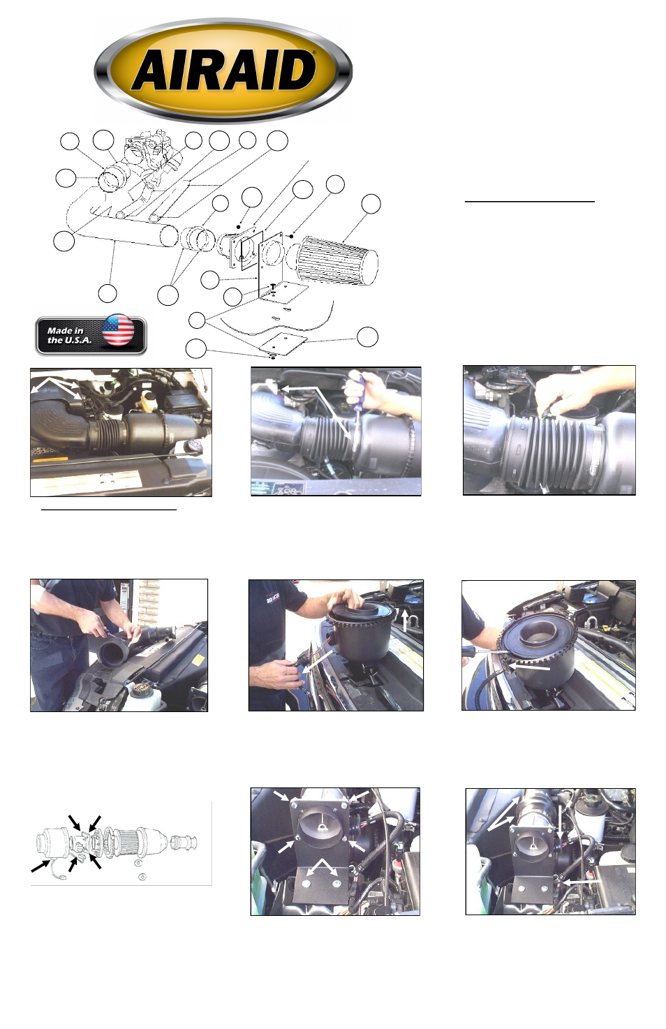
Component Identification
1.
Airaid Premium Filter
1
2.
Airaid Intake Tube
1
3.
MAF Bracket
1
4.
Urethane Hump Hose
1
5.
Urethane Reducer Hose
1
6.
5/8” x 18” Breather Hose
1
7.
3/4” x 12” L-Hose
1
8.
1/4- 20x 7/8” Hex Bolts
6
9.
1/4” Flat Washer
4
10.
1/4- 20” Nylock Nuts
6
11.
MAF Gasket
1
12.
MAF Backing Plate
1
13.
#60 Hose Clamp
3
14.
#52 Hose Clamp
1
15.
7/16” Rubber Grommet
1
16.
Black Speed Clamp
2
17.
Black Speed Clamp
2
2. Loosen the hose clamps at the throttle body,
and air filter housing outlet.
3. Remove the crankcase breather hose from the
factory intake tube and the valve cover. Discon-
nect the Air Intake Temperature (AIT) sensor
wiring harness from the sensor. (4.6L Engine
only: Disconnect the Idle Air Bypass Valve
(IABV) inlet tube from the factory intake tube.)
(5.4L Engine only: disconnect the IABV, save the
plastic hose for reuse.)
1. Disconnect the negative battery cable.
Using a 10mm socket, remove the three bolts secur-
ing the engine beauty cover, remove the cover, and
set it aside (save the bolts and cover for reuse).
7. Using a 10mm socket, remove the four MAF
sensor mounting nuts. Carefully remove the MAF
sensor and the wiring harness from the airbox, (save
them for reuse).
8. Mount the MAF sensor to the MAF bracket
(#3) using four 1/4-20x 7/8” hex bolts (#8), 1/4-
20” nylock nuts (#10), and the MAF gasket
(#11). Mount the bracket and sensor to the facto-
ry location, using the MAF backing plate (#12),
two 1/4-20x 7/8” hex bolts (#8), four 1/4” flat
washers (#9), and two 1/4- 20” nylock nuts
(#10). (Leave the MAF bracket loose for now).
9. Reconnect the MAF sensor wiring harness to
the sensor, and to the main engine wiring har-
ness. Install the urethane hump hose (#4) onto
the MAF sensor, with two #60 hose clamps
(#13). Tighten only the clamp on the sensor.
5. The factory airbox assembly is held in place by
rubber grommets (it is a “pull to release fit.”). Re-
move the assembly and grommets from the engine
compartment. Unlatch the airbox and separate the
two sections. Remove the wire loom from the
MAF sensor wir ing har ness, then slide the
grommet away from the connector.
6. Locate the notch on the flat side of the airbox
and gently pry it up. Disconnect the MAF sensor
wiring harness from the sensor (inside the air-
box).
4. ) Remove the factory intake tube, and set it aside.
Remove the AIT sensor from the tube by carefully
prying it out with a flat blade screwdriver (save the
sensor for reuse). Disconnect the Mass Air Flow
(MAF) sensor wir ing har ness fr om the main en-
gine wiring harness.
Disconnect the MAF
sensor wiring harness
located inside the air-
box.
#2
#1
#3
#4
#5
#16
#7
#8
#10
#11
#12
#8
#9
#10
#14
#13
#13
#15
#17
#6
OEM Mass Air Flow Sensor