Airaid 400-101 User Manual
Installation instructions, Component identification, For part numbers
Installation Instructions
For Part Numbers:
400-101
720-478 Airaid Oiled Media Filter
401-101
721-478 SynthaMax Dry Media Filter - Red
402-101
722-478 SynthaMax Dry Media Filter - Black
403-101
723-478 SynthaMax Dry Media Filter - Blue
2011-2014 Ford F-150 3.5L
EcoBoost V6
2. Disconnect the wiring harness from air sensor in the
air box lid. Unclip the air box lid and remove it and the
factory air filter from the vehicle. The lower half of the
factory air box is to remain in the vehicle.
3. On 2011 models with the vacuum line in the intake,
install the 1/4” Barbed Fitting. The Plug will not be used.
On 2012-2014, Install the 1/4” Plug into the Airaid In-
take Tube as shown.
4. Slide the Couplers and Clamps onto the Intake tube as
shown.
5. Install the Airaid Intake Tube onto the factory turbo
plumbing and tighten the Clamps. On 2011 models,
reconnect the vacuum from step 1 to the Fitting in-
stalled in step 3.
6. Assemble the Front and Rear Panels as shown with the
tabs on the outside of the assembly. Use the four 6-32
Button Head Screws, #6 Flat Washers , and #6 Kep Nuts
to secure the assembly.
8. If your vehicles intake utilizes a MAP sensor, Re-
move the MAP Plug and transfer the MAP sensor into
the Airaid Tube as shown. Secure the sensor using the
Long, 8-32 Button Head Screw and the #8 Washer.
Discard the Plug.
7. Depending on the configuration of your factory intake
system, you will use one of the two sensor receptacles in
the Airaid Sensor Tube. There is a Mass Airflow sensor
receptacle on the Tube and a MAP sensor receptacle on
the Tube. Both ports are capped and plugged from the
factory.
9. If your vehicles intake utilizes a Mass Air flow , or
MAF sensor, Remove the MAF Cap and Gasket and
transfer the sensor into the Airaid Tube as shown. A Torx
Bit has been supplied in the hardware pack aid in remov-
al. Secure the sensor by reusing the Two 8-32 Button
Head Screws. Discard the Cap and Gasket.
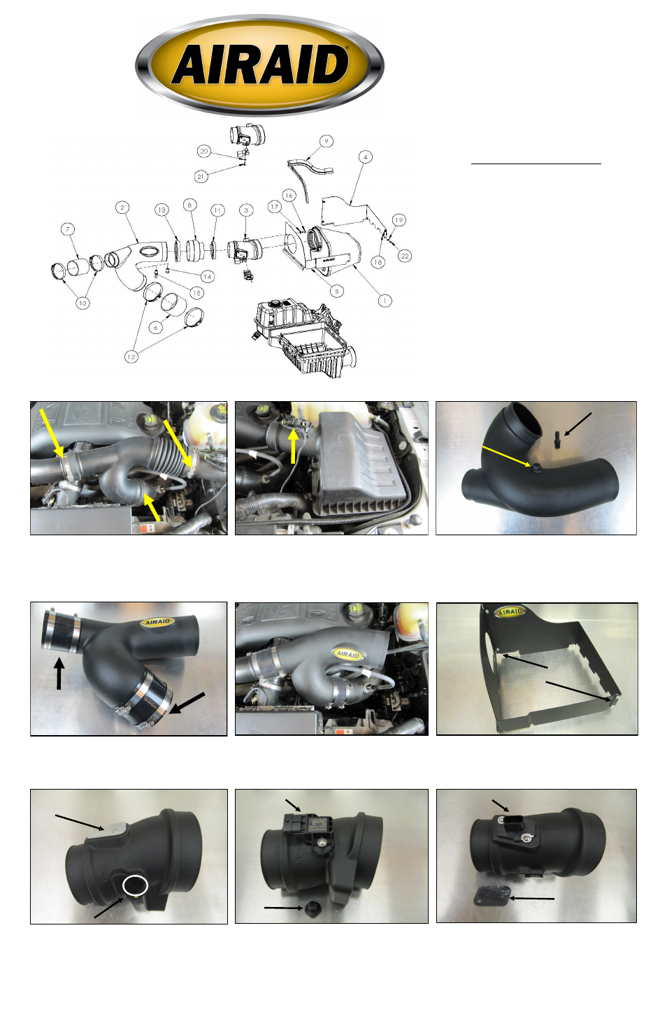
Component Identification
1
AIRAID PREMIUM AIR FILTER
1
2
INTAKE TUBE
1
3
SENSOR TUBE
1
4
REAR PANEL
1
5
FRONT PANEL
1
6
4” COUPLER
1
7
3” COUPLER
1
8
HUMP HOSE
1
9
WEATHER STRIP, 22"
1
HARDWARE AND INSTRUCTIONS
1
10
#48 HOSE CLAMP
2
11
#56 HOSE CLAMP
1
12
#64 HOSE CLAMP
2
13
#68 HOSE CLAMP
1
14
1/4 NPT PLUG
1
15
1/4 NPT BARBED FITTING
1
16
1/4-20 x 1/2” BUTTON HEAD SCREW
2
17
1/4" FLAT WASHER
2
18
6-32 KEP NUT
4
19
#6 FLAT WASHER
4
20
#8 FLAT WASHER
1
21
8-32 BUTTON HEAD SCREW
1
22
6-32 PAN HEAD SCREW
4
23
T20 TORX BIT
1
1.
Disconnect The Negative Battery Terminal.
Loosen the 3 clamps on the factory intake tube and re-
move it from the vehicle.
NOTE: 2011 models will have a vacuum line attached to
the underside of the intake tube that will need to be dis-
connected.
Full color instructions can be viewed on our web site at Airaid.com. Use the Product Search function to find your part number, and click View Details.
Tabs on outside
MAF CAP
MAP PLUG
MAP Sensor
PLUG
MAF Sensor
CAP
Plug
Fitting
4” Coupler
& # 64
Clamps
3” Coupler &
#48 Clamps
Tabs on outside