Airaid 400-140-2 User Manual
Installation instructions, Component identification, For part numbers
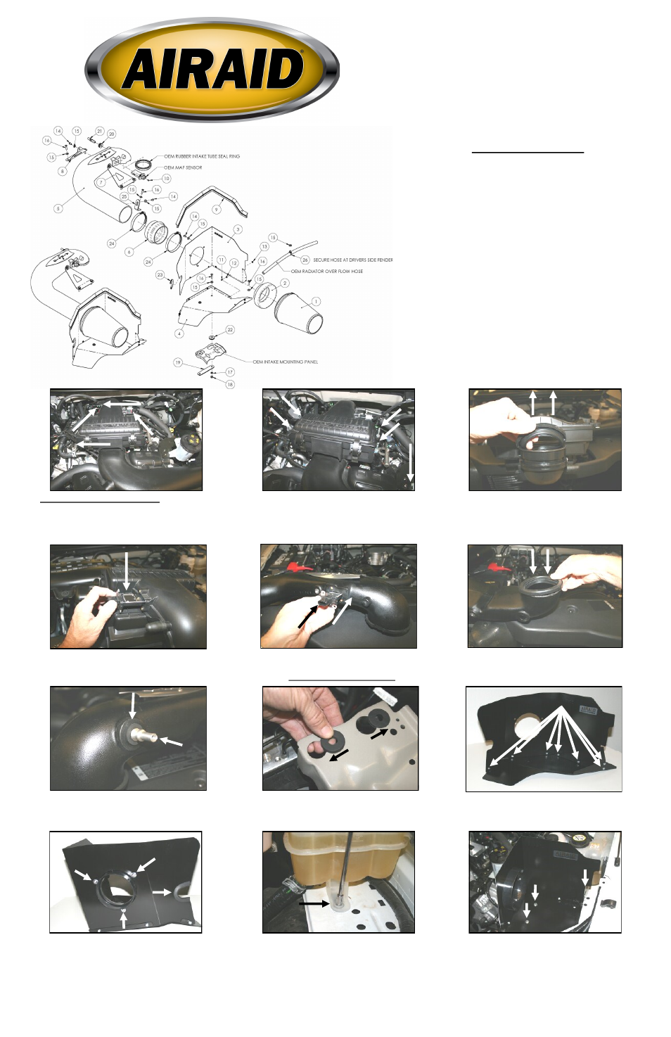
11. Using a 5/16” socket, remove one bolt from the facto-
ry coolant reservoir mount.
12. Install the CAD into the vehicle with one 6mm bolt (#16)
and 1/4” flat washer (#15) through the panel, through the cool-
ant reservoir mount and into the speed nut below it. Using two
6mm bolts (#16) two ¼” flat washers (#15), two ¼” lock
washers (#17), and two M6 hex nuts (#18), insert the two bolts
thru the CAD, thru the grommets, and thru the long/narrow
bracket (#19). Use the line drawing above for reference.
Component Identification
1.
Airaid Premium Filter
1
2.
Air Filter Adapter
1
3.
MAF Panel Coated
1
4.
Bottom Panel Coated
1
5.
Airaid Intake Tube
1
6.
Urethane Hump Hose
1
7.
Drivers Side Bracket
1
8.
Passenger Side Bracket
1
9.
Weather Strip 26 1/2”
1
10.
8-32 x 3/8” Button Head Screw 2
11.
6-32 x 5/16” Screw
7
12.
#6 Flat Washer
7
13.
6-32 Keps Nut
7
14.
¼-20 x 1/2” Button Head Bolt
6
15.
¼” Flat Washer
15
16.
M6-1x25 Hex Bolt
8
17.
1/4” Lock Washer
2
18.
M6 Hex Nut
2
19.
Long/Narrow Bracket
1
20.
Rubber Grommet
1
21.
Aluminum Fitting
1
22.
Rubber Grommet
2
23.
Rubber Trim 4”
1
24.
#72 Hose Clamp
2
25.
L-Shaped bracket
1
26.
Black Plastic Hose Mount
1
27.
T-20 Security Bit
1
2. Using a 10mm deep socket, remove the 4 tower bolts, two
on each side of the factory airbox. Remove one bolt holding
the factory intake tube to the mounting bracket. Remove the
complete factory intake system.
Installation Instructions
For Part Numbers:
400-140-2
700-469 Airaid Oiled Media Filter
401-140-2
701-469 SynthaMax Dry Media Filter - Red
402-140-2
702-469 SynthaMax Dry Media Filter - Black
403-140-2
703-469 SynthaMax Dry Media Filter - Blue
2004-08 Ford F-150 5.4L V8
2006-08 Lincoln LT 5.4L V8
3. Remove the rubber seal from the factory airbox and save
it for re-installation in step #6.
9. Assemble the two Cool Air Dam (CAD) panels (#3, #4)
using seven 6-32 x 5/16” screws (#11), #6 flat washers (#12),
and 6-32 keps nuts (#13).
8. Slip two rubber grommets (#22) into the large holes in the
bracket on the drivers side fender, then slide them sideways
into the smaller holes as shown.
10. Install the air filter adapter (#2) into the CAD using three ¼ -
20 x 1/2” button head bolts (#14) and ¼” flat washers (#15).
Next, install the 4” rubber trim (#23), as shown.
1. Disconnect the negative battery cable.
Push the green tab, and disconnect the factory breather line
from the intake tube. Slide the red tab, and disconnect the Mass
Air Flow (MAF) sensor wiring harness from the sensor.
Unclip the battery cable from the front of the factory airbox.
7. Install the rubber grommet (#20) into the Airaid Intake Tube,
and then install the aluminum fitting (#21) into the grommet,
tapered end first.
4. Using the provided T-20 Security Bit, remove the two
screws, and remove the MAF sensor from the factory intake
tube. Save the sensor for re-installation in the next step.
5. Re-install the MAF sensor into the Airaid Intake Tube
(#5) using two 8-32 x 3/8” button head screws (#10). Do not
over tighten! Do Not Use The Factory Screws!!
6. Re-install the rubber seal removed in step #3 onto the Airaid
Intake Tube. Use caution to align the notch in the tube with the
notch in the seal.