Airaid 400-239-1 User Manual
Installation instructions, Component identification
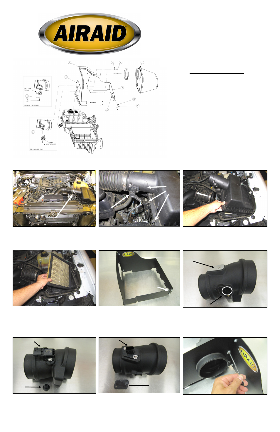
2. A. Disconnect the Air meter in the factory airbox
top.
B. Unfasten the Three clips on the left side of the air-
box.
3. Slide the factory intake away from the airbox. Lift up
and slide the airbox tabs out of the slots in the lower half
and set aside.
4. Remove the Factory air filter.
5. Assemble the Front and Rear Panels (# 3 & #4)
as shown with the tabs on the outside of the assembly.
Use the four 6-32 Button Head Screws (#9), #6 Flat
Washers (#12), and #6 Kep Nuts (#11) to secure the
assembly.
9. Install the Air Meter Tube (#2) into the Panel Assem-
bly and secure using the two 1/4-20 Button Head Screws
(#6),and 1/4” Flat Washers (#10).
A.
B.
Component Identification
1.
Airaid Premium Filter
1
2.
Air Meter Tube
1
3.
Rear Panel
1
4.
Front Panel
1
5.
Weather Strip 22”
1
6.
1/4-20 x 1/2” Button Head Bolt
2
7.
#8-32 x 5/8” Button Head Screw
1
8.
#8 Washer
1
9.
6-32 x 5/16” Pan Head Screw
4
10.
1/4” Flat Washer
2
11.
#6 Kep Nut
4
12.
#6 Flat Washer
4
13.
T-20 Torx Bit
1
NOTE: These instructions depict an installation being per-
formed on a 5.0L F-150 and is meant to be a guide for all
other makes and models listed. While some details may
vary from vehicle to vehicle, the general install procedure
remains the same.
Disconnect The Negative Battery Terminal!
1. Loosen the hose clamp on the airbox side of the fac-
tory air intake tube.
Tabs on outside
Installation Instructions
For Part Numbers:
400-239-1
720-478 Airaid Oiled Media Filter
401-239-1
721-478 SynthaMax Dry Media Filter - Red
402-239-1
722-478 SynthaMax Dry Media Filter - Black
403-239-1
723-478 SynthaMax Dry Media Filter - Blue
2011-14 Ford F-150 3.5L, 3.7L and 5.0L Motors
2010-14 Ford SVT Raptor 6.2L
2011-15 Ford F-250/ 350 Superduty 6.2L
METER CAP
MAP PLUG
6. Depending on the sensor configuration of your factory
intake system, you will use one of the two sensor recep-
tacles in the Airaid intake tube. There is a Mass Airflow
sensor receptacle on the tube and a MAP sensor recepta-
cle on the tube. Both ports are capped and plugged from
the factory.
7. If your vehicles intake utilizes a MAP sensor, Re-
move the MAP Plug and transfer the MAP sensor into
the Airaid intake tube as shown. Secure the sensor us-
ing the Long 8-32 Button Head Screw (#9) and the #8
Washer (#8). Discard the Plug.
8. If your vehicles intake utilizes a Mass Airflow , or
MAF sensor, Remove the Meter Cap and Gasket and
transfer the sensor into the Airaid intake tube as shown.
Secure the sensor by reusing the Caps Two 8-32 Button
Head Screws. Discard the Cap and Gasket.
MAP Sensor
PLUG
MAF Sensor
CAP
Full color instructions can be viewed on our web site at Airaid.com. Use the Product Search function to find your part number, and click View Details.