Airaid 450-174 User Manual
Installation instructions, Component identification
Installation Instructions
For Part Numbers:
450-174
700-461 Airaid Oiled Media Filter
451-174
701-461 SynthaMax Dry Media Filter - Red
452-174
702-461 SynthaMax Dry Media Filter - Black
453-174
703-461 SynthaMax Dry Media Filter - Blue
2012-13 Boss 302 Mustang
5.0L V8
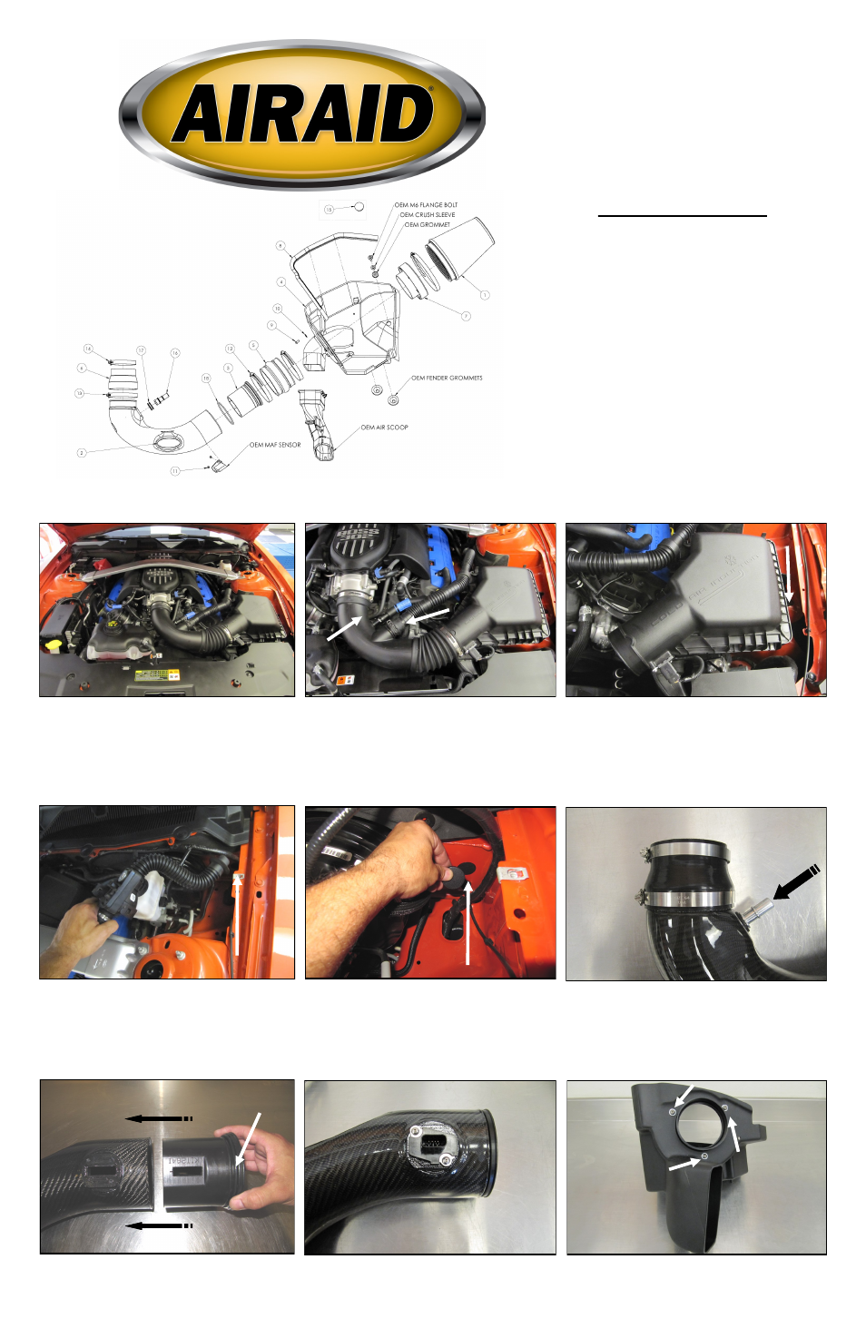
2. A) Loosen the hose clamps on the factor y intake
tube B) Squeeze the clamp and disconnect the resonator
from the air intake tube. C) Carefully depress the hose
lock tab and disconnect the crank case breather line .
D) Remove the factor y intake tube.
3. A) Slide the r ed tab out of the connector and dis-
connect the Mass Air Flow sensor. Carefully pry the har-
ness anchor from the air box using a standard screwdriv-
er. B) Separate the resonator tube from the stand off at-
tached to the Air box lid. C) Using a 10mm socket, re-
move the bolt securing the air box to the inner fender and
remove the air box assembly. This bolt will be reused in
step 12.
4. Unbolt the Intake resonator from the inner fender and
disconnect it at the drivers side firewall. Remove the
entire assembly from the vehicle and set it aside. It will
not be reused.
5. Plug the resonator hole in the firewall with the Fire-
wall Plug (#15).
6. A.) Install the Silicone Reducer (#6) and Hose
clamps onto the Airaid Intake Tube (#2). Place the #56
clamp (#14) on the Throttle body side of the reducer, and
the #64 clamp (#13) on to the tube side.
B.) Inser t the 5/8” Gr ommet (#17) into the Intake
tube as shown. Complete the tube assembly by inserting
the 5/8 Aluminum Fitting (#16) into the Grommet.
8. Install the Mass Air Flow sensor into the intake tube
using two provided 8-32x3/8” screws (#11).
7. Slide the Modular Venturi Tube (#3) into the Airaid
Intake tube (#2). Make sure to align the two slots for the
Mass Air Flow sensor and that the O Ring (#18) is in
Place.
9. Install the Filter Adapter (#7) onto the Airaid Cool Air
Box (#4) as shown.
Use the three 1/4-20 button head bolts (#9), and flat
washers (#10) to secure the Adapter.
A.
B.
Component Identification
1.
Airaid Premium Filter
1
2.
Airaid Intake Tube
1
3.
Modular Venturi Tube (MVT)
1
4.
Cool Air Box
1
5.
Urethane Hump Hose
1
6.
Silicone Reducer
1
7.
Filter Adapter
1
8.
Weather strip 25”
1
9.
¼-20 Button Head Bolt
3
10.
¼” Flat Washer
3
11.
8-32x3/8” Button Head Screw
2
12.
#72 Hose Clamp
2
13.
#64 Hose Clamp
1
14.
#56 Hose Clamp
1
15.
Firewall Plug*
1
16.
5/8 Aluminum Fitting
1
17.
5/8 Grommet
1
18.
174 O Ring
1
19.
#20 Torx Bit
1
INSTALL NOTE:
If you are installing this kit on a vehicle
equipped with a
Power Dome Hood with Heat Extractors
we
suggest the use of our optional AIRAID pre-filter (Part #799-469)
to give an added layer of protection from the elements
Disconnect The Negative Battery Terminal!
1.Make sure the ignition switch is turned off and the
parking brake has been set.
B.
A.
C.
O Ring
Full color instructions can be viewed on our web site at Airaid.com. Use the Product Search function to find your part number, and click View Details.