Airaid 450-204 User Manual
Installation instructions, Component identification
Installation Instructions
For Part Numbers:
450-204
700-462 Airaid Oiled Media Filter
451-204
701-462 SynthaMax Dry Media Filter - Red
452-204
702-462 SynthaMax Dry Media Filter - Black
453-204
703-462 SynthaMax Dry Media Filter - Blue
1999-04 Ford Mustang GT
4.6L V8
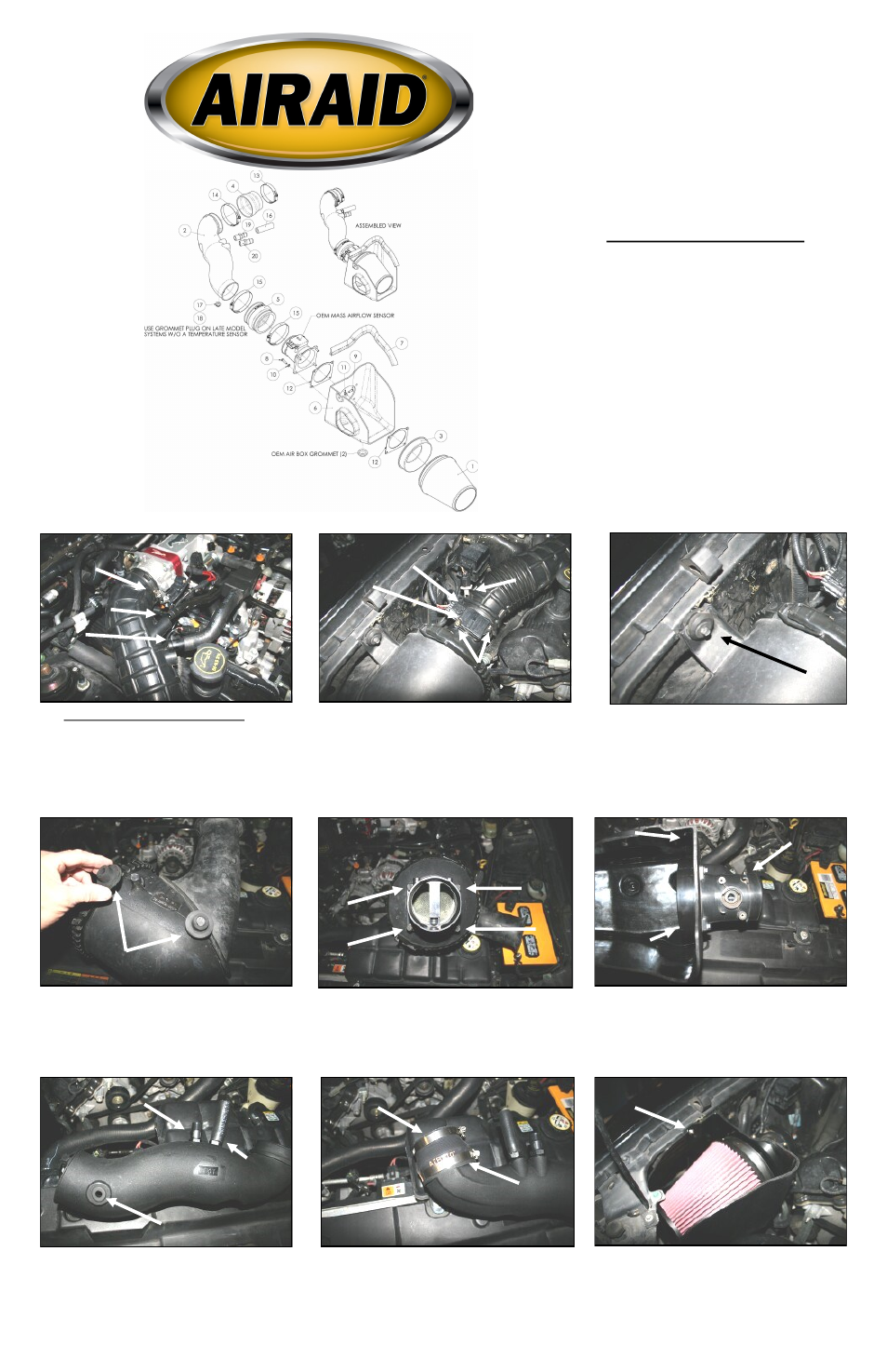
1. Disconnect the negative battery cable.
A.) Loosen the hose clamp on the factory intake tube
at the throttlebody. B.) Disconnect the crankcase
breather tube from the factory air intake tube. C.) Dis-
connect the idle bypass hose from the factory air in-
take tube and remove the hard plastic 3/4” coupler
from inside the rubber hose.
2. A.) Loosen the factory intake tube hose clamp on
the Mass Air Flow (MAF) sensor housing. B.) Care-
fully remove the intake air temperature sensor from
the factory intake tube(1999-01 models). C.) Using
the supplied T-20 torx bit, remove two screws, and
remove the MAF sensor from the MAF housing. Set
the temp sensor and MAF sensor to the side for rein-
stallation later.
3. Remove the bolt that holds the factory air filter
canister to the inner fender. Next remove the factory
air intake tube from the throttlebody, and then the
MAF housing. Now with a twisting motion r e-
move the factory air filter canister from the vehicle.
4. Remove the two factory grommets from the bottom
of the factory air filter canister and reinstall them into
the holes in the inner fender.
5. Remove the four bolts that hold the MAF housing to
the factory air filter canister. The bolts will not be re-
used, but the MAF housing will be used in the next
step.
6. Mount the factory MAF housing to the Airaid Cool
Air Dam (#6) using four 6mmx25mm bolts (#8),
four lock washers (#10), two MAF gaskets (#12), and
one velocity stack (#3). Refer to the line drawing at
the top of this page for the proper sequence of how to
install the parts.
8. Install the reducer coupler (#4) onto the throttle-
body end of the Airaid Intake Tube using the #56
hose clamp (#14) on the tube end, and the #44 hose
clamp (#13) on the small end. Tighten only the large
#56 clamp at this time.
Component Identification
1.
Airaid Premium Filter
1
2.
Airaid Intake Tube
1
3.
Velocity Stack
1
4.
Reducer Coupler
1
5.
Hump Hose
1
6.
Cool Air Dam
1
7.
Weather Strip 17”
1
8.
M6 - 1 x 25mm Hex Bolt
4
9.
M6 x 20mm Button Head Bolt
1
10.
¼” Lock Washer
4
11.
¼” Flat Washer
1
12.
MAF Gasket
2
13.
#44 Hose Clamp
1
14.
#56 Hose Clamp
1
15.
#60 Hose Clamp
2
16.
5/8” x 3” Hose
1
17.
Grommet
1
18.
Plug Grommet
1
19.
1/2” NPT x 5/8” Barb
1
20.
1/2” NPT x 3/4” Barb
1
21.
T-20 Security Torx Bit
1
7. If your vehicle is equipped with an intake temp
sensor (1999-01), install the supplied grommet (#17)
into the hole in the Airaid Intake Tube (#2), On later
models (2002-04), install the grommet plug (#18) .
Next install the two barbed fittings (#19 & #20) into
the tube as shown. Now install the 5/8”x 3” hose (#16)
onto the 5/8” barbed fitting.
9. Install the Airaid Premium Filter (#1) onto the ve-
locity stack inside of the CAD as shown and tighten
the clamp. Next install the CAD assembly into the
vehicle aligning the grommet posts into the factory
grommets in the inner fender. Now secure the CAD to
the inner fender well using the 6mmx20mm button
head bolt (#9), and flat washer (#11).
A.
B.
C.
A.
B.
C.
MAF sensor
Velocity Stack
MAF Housing
CAD
Grommet or Plug
3/4” Barbed Fitting
5/8” Barbed Fitting
and Hose
6mmx20mm Button Head
#44 Hose Clamp
#56 Hose Clamp