Airaid 450-211 User Manual
Installation instructions, Component identification
Installation Instructions
For Part Numbers:
450-211
700-469 Airaid Oiled Media Filter
451-211
701-469 SynthaMax Dry Media Filter - Red
452-211
702-469 SynthaMax Dry Media Filter - Black
453-211
703-469 SynthaMax Dry Media Filter - Blue
2007-09 Ford Mustang Shelby GT
Supercharged 5.4L V8
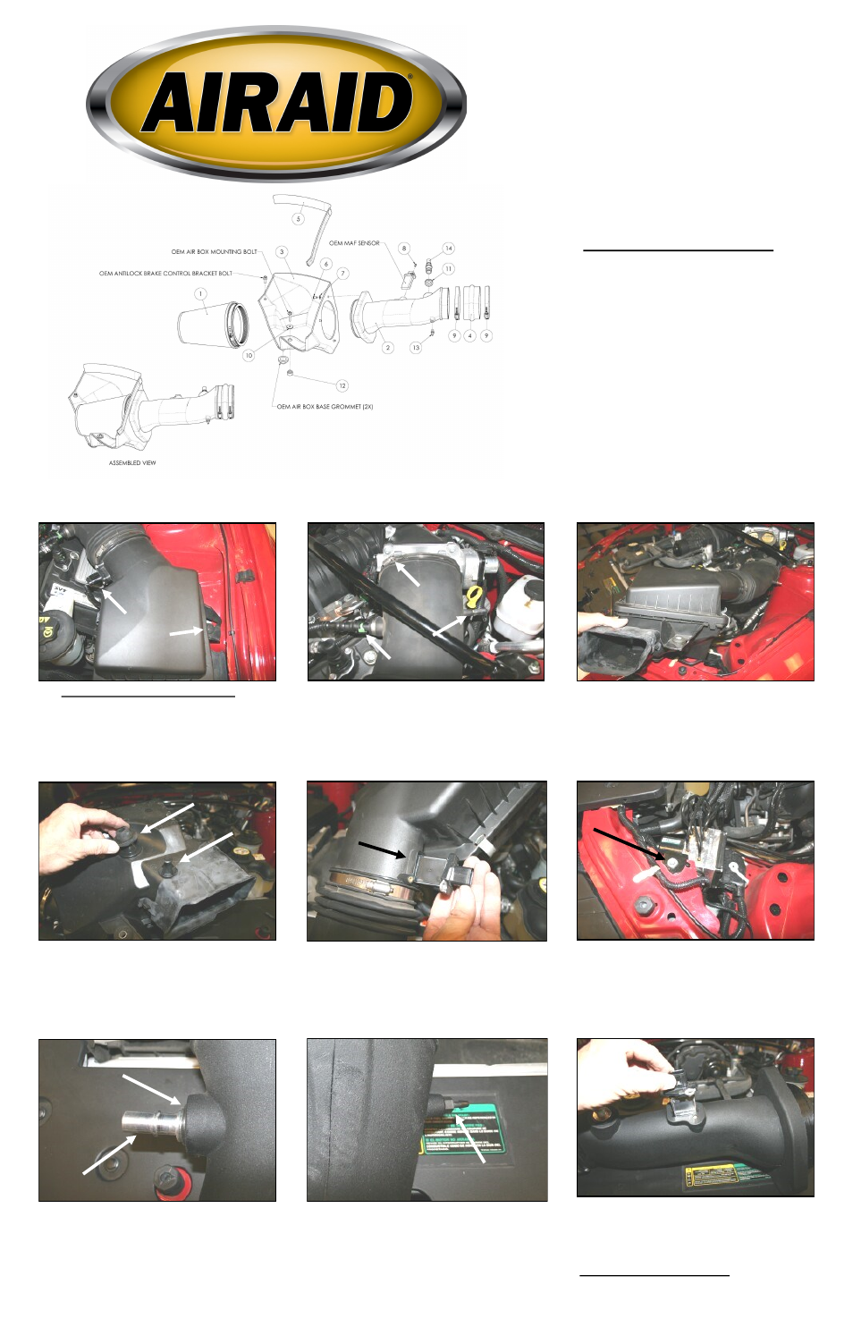
1. Disconnect the negative battery cable.
A.) Slide out the RED locking tab on the bottom of
the Mass Air Flow sensor (MAF) connector, and then
squeeze the BLACK tab and disconnect the connect-
or from the sensor. B.) Using a 10mm socket, re-
move and save the bolt that holds the air filter box to
the inner fender. It will be reinstalled in step #13.
2. A.) Loosen the factory intake tube hose clamp on
the throttle body. B.) Push the GREEN tab on the
breather hose connector and disconnect it from the
factory intake tube. C.) CAREFULLY disconnect the
vacuum line from the factory intake tube.
3. Remove the complete factory intake system from
the vehicle.
4. Remove the two factory grommets from the bot-
tom of the factory airbox and replace them back into
the holes in the inner fender. They will be used to
guide the Airaid Cool Air Dam to the correct location
in the vehicle.
5. Using the provided #20 torx bit, remove two facto-
ry screws and the Mass Air Flow sensor from the fac-
tory airbox lid. Note the direction of the sensor for
proper re-installation later. (Save the mass air sensor
for re-installation in step #9, the factory screws will
not be re-used).
6. Using a 10mm socket, remove and save the bolt
from the top of the anti-lock brake bracket. It will be
re-installed later in step #13.
8. Install the 1/8”NPT x 3/16” barbed fitting (#13)
into the small threaded hole in the side of the Airaid
Intake Tube.
Component Identification
1.
Airaid Premium Filter
1
2.
Airaid Intake Tube
1
3. Cool Air Dam
1
4. Oval Hump Hose
1
5. Weather Strip 25 1/2”
1
6.
¼-20x1/2” Button Head Bolt
3
7.
¼” Flat Washer
3
8.
8-32x3/8” Button Head Screw
2
9.
#80 Hose Clamp
2
10.
1/4” Fender Washer
1
11.
Grommet
1
12.
Aluminum Spacer
1
13.
1/8”NPT x 3/16” Barbed Fitting
1
14.
Aluminum Fitting
1
15.
#20 Torx Bit
1
7. Install the provided grommet (#11) into the large
hole in the side of the Airaid Intake Tube (#2). Next,
carefully install the supplied aluminum fitting (#14)
into the grommet as shown.
9. Install the Mass Air Flow sensor removed in step
#5, into the Airaid Intake Tube using the provided 8-
32 x 3/8” button head screws (#8). Make sur e the
arrow on the sensor is pointing towards the throttle-
body.
Do Not Use The Factory Screws!
A.
B.
A.
B.
C.
Grommet
Aluminum fitting
Full color instructions can be viewed on our web site at Airaid.com. Use the Product Search function to find your part number, and click View Details.