Airaid 450-234 User Manual
Installation instructions, Component identification, For part numbers
Installation Instructions
For Part Numbers:
450-234
720-448 Airaid Oiled Media Filter
451-234
721-448 SynthaMax Dry Media Filter - Red
452-234
722-448 SynthaMax Dry Media Filter - Black
453-234
723-448 SynthaMax Dry Media Filter - Blue
2008-10 Ford Focus 2.0L I-4
Non PZEV Vehicles
1. Disconnect the negative battery cable!
Remove the three bolts that secure the intake scoop to
the radiator support. The two long bolts will be reused
in step #14.
2. A.) Pull the r ed tab on the bottom, and then
squeeze the Mass Air Flow sensor wiring connector
and disconnect it from the sensor. B.) Push the tab, and
disconnect the breather hose from the plastic elbow. C.)
Loosen the two factory clamps on the flexible intake
tube. D.) Remove the Oetiker clamp, and then carefully
remove the small plastic elbow from the flexible intake
tube leaving the breather hose connected to the elbow.
3. Remove the factory flexible intake tube from the vehicle.
Remove the Oeticker clamp, and then remove the large
plastic elbow from the flexible intake tube. It will be
reused in step #12.
4. Pull straight up, and remove the airbox assembly
from the vehicle. It is only held in by one grommet at
this point.
5. Remove the scoop from the factory airbox. Next, us-
ing the supplied #20 Torx bit, remove the Mass Air
Flow sensor from the airbox lid. These parts will be re-
installed in steps #10 & 13.
6. Remove one bolt that secures the brace to the inner
fender. It will be reinstalled in step #15.
7. Install the supplied hump hose (#6), and two #44
hose clamps (#16) onto the throttlebody as shown.
Tighten only the clamp on the throttlebody.
8. Install the small grommet (#20) into the hole on the
top of the Airaid intake tube (#2). Now install the large
grommet (#21) into the hole on the side of the tube.
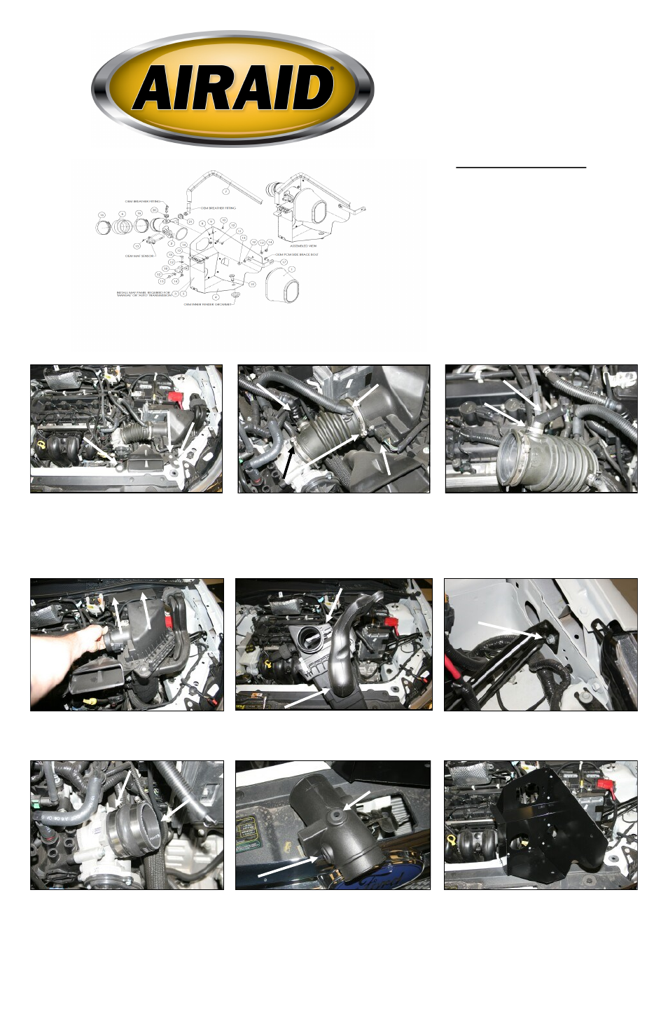
Component Identification
1.
Airaid Premium Filter
1
2.
Airaid Intake Tube
1
3.
MAF Panel (Auto Trans)
1
4.
Bottom Panel
1
5.
MAF Panel (Manual)
1
6.
Hump Hose
1
7.
Weather Strip 22”
1
8.
6-32x5/16” Phillips Screw
7
9.
#6 Flat Washer
7
10.
6-32 Keps Nut
7
11.
1/4”-20 Button Head Bolt
2
12.
1/4” Flat Washer
7
13.
1/4”-20x5/8” Hex Bolt
3
14.
1/4”-20 Lock Nut
3
15.
8-32 x 3/8” Button Head Screw 2
16.
#44 Hose Clamp
2
17.
Side Bracket
1
18.
Front Bracket
1
19.
Billet Rivet
1
20.
Small Grommet
1
21.
Large Grommet
1
22.
T20 Torx Bit
1
A
.
B
.
C
.
D
.
A
.
B
.
9. Auto Transmission vehicle only: Assemble the
two Cool Air Dam panels (#3 & #4) using 7 screws
(#8), washers (#9), and nuts (#10) as shown. Make sure
that the bent flanges where the panels screw together,
are on the outside of the box. Note: Use panel #3 with
tag marked “AUTO”.
Manual Transmission vehicle only: Assemble the
two Cool Air Dam panels (#4 & #5) using 7 screws
(#8), washers (#9), and nuts (#10) as shown. Make sure
that the bent flanges where the panels screw together,
are on the outside of the box. Note: Use panel #5 with
tag marked “Manual”.