Airaid 450-238 User Manual
Component identification
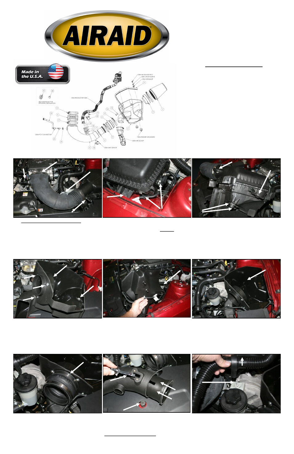
Installation Instructions
For Part Numbers:
450-238
700-461 Airaid Oiled Media Filter
451-238
701-461 SynthaMax Dry Media Filter - Red
452-238
702-461 SynthaMax Dry Media Filter - Black
453-238
703-461 SynthaMax Dry Media Filter - Blue
2010 Ford Mustang GT
4.6L V8
1. Disconnect the negative battery cable.
A.) Push the gr een plastic tabs on each end, and r e-
move the breather hose from vehicle. (Save for later use).
B.) Loosen the hose clamp that secur es the intake tube
to the throttlebody. C.) Squeeze the clamp and disconnect
the resonator from the air intake tube. D.) Slide the red
tab, and disconnect the wiring harness from the Mass Air
Flow sensor (MAF).
2.A.) Using a 10mm socket, r emove and save the bolt
that secures the airbox to the fender.
B.) Using a flat blade scr ewdr iver , carefully, push, or
pry the 5 wiring loom anchors from the factory airbox.
3. Grab the airbox and tube and roll it forward while lift-
ing up to dislodge it from the intake scoop. Remove the
assembly from the vehicle. A.) Remove the two factory
grommets and then replace them back into the two holes
in the inner fender. B.) Remove the steel sleeve and
grommet and save for reinstallation later. C.) Using the
provided #20 Torx bit, remove the two screws and the
MAF sensor fr om the tube.
4. A.) Install the filter adapter (#9) using thr ee 1/4-20
button head bolts (#12), and flat washers (#13) into the
Airaid Cool Air Dam (CAD) (#4) as shown. B.) Reinstall
the small grommet and sleeve (removed in step #3) into
the hole in the CAD.
5. Turn the CAD so that the bottom faces the left fender
as shown. Now reinstall the wiring loom anchors into
their respective holes starting at the back of the CAD
with the two hole anchor and work your way underneath
and towards the front. The last anchor nearest the MAF
sensor is not anchored.
6. Install the CAD into the vehicle making sure that the
scoop provision in the CAD aligns with the factory
scoop, and the two locating pins on the bottom align with
the factory grommets. Next reinstall the factory bolt that
was removed in step #2 thru the steel sleeve and grommet
and into the inner fender. Make sure that the wiring har-
ness is not pinched under the CAD.
8. Slide the Modular Venturi Tube (#3) into the Airaid
intake tube (#2) making sure to align the two slots for
the MAF sensor. Next install the MAF sensor into the
intake tube using two provided 8-32x3/8” screws (#14).
Do Not Use The Factory Screws!
Component Identification
1.
Airaid Premium Filter
1
2.
Airaid Intake Tube
1
3.
Modular Venturi Tube (MVT)
1
4.
Cool Air Dam
1
5.
Urethane Hump Hose
1
6.
Urethane Oval Coupler
1
7.
Urethane 1 3/4” Coupler
1
8.
Urethane Cap*
1
9.
Filter Adapter
1
10.
3/8”x12” Hose
1
11.
Weather Strip 25”
1
12.
¼-20 Button Head Bolt
3
13.
¼” Flat Washer
4
14.
8-32 x 3/8” Button Head Bolt
2
15.
1/4-20 Hex Head Bolt
1
16.
6mm x 12mm Hex Bolt
1
17.
#72 Hose Clamp
4
18.
40-60mm Hose Clamp
2
19.
Grommet
1
20.
Firewall Plug*
1
21.
Aluminum Fitting
1
22.
Resonator Tube Bracket
1
23.
#20 Torx Bit
1
7. Install the provided hump hose (#5) onto the filter
adapter using two #72 hose clamps (#17) as shown.
Leave the two hose clamps loose for now.
9. Lift up on the intake resonator tube to disengage it
from the stud securing the power steering reservoir. Us-
ing a deep 10mm socket, remove the stud and save it for a
possible optional install. See step #18.
A.
B.
C.
A.
B.
D.
A.
B.
C.
A.
B.